Double-loop control system with single hydraulic motor

a control system and hydraulic motor technology, applied in mechanical equipment, servomotors, transportation and packaging, etc., can solve the problems of hydraulic system failure, potential energy generation, low working efficiency of an entire system, etc., and achieve high energy efficiency and simple system. the effect of convenien

Active Publication Date: 2016-10-20
TAIYUAN UNIV OF TECH
View PDF4 Cites 8 Cited by
  • Summary
  • Abstract
  • Description
  • Claims
  • Application Information

AI Technical Summary

Benefits of technology

[0021](3) the system is simple and convenient, and the energy efficiency is high.

Problems solved by technology

Therefore, system pressure and displacement must be determined to select a hydraulic motor according to a maximum torque during working, which often increases a volume of the hydraulic motor and a volume of a corresponding hydraulic control system, which results in lower working efficiency of an entire system.
During rotating, lifting and traveling processes of the conventional hydraulic valve control mechanism, kinetic energy generated by rotating-braking or decelerating braking, potential energy generated during falling or traveling downhill are wasted by being transformed into heat of oil through a throttling effect of valves, and the heat is also a main reason causing hydraulic systems failure.
In order to reduce the heating, an additional cooling system is needed to cool the oil, which further increases the systems energy consumption.
However, the shortcomings of it are that this method is only applicable to hybrid power machines, and cost is high.
However, the accumulator state will affect the operating speed characteristics during rotating, and the stored energy cannot be fully used.
However, a storage loop and a control loop of the system can't drive the hydraulic motor at the same time, and when the storage loop individually drives the hydraulic motor, the power is insufficient, which will affect the recycling effect.
But all of the above technologies are not able to use only one hydraulic motor to satisfy different work conditions and different load driving requirements with advantages such as simple structure, high system reliability, and high energy efficiency at the same time.

Method used


Image

  • Double-loop control system with single hydraulic motor
  • Double-loop control system with single hydraulic motor
  • Double-loop control system with single hydraulic motor

Examples


embodiment 1

Preferred Embodiment 1

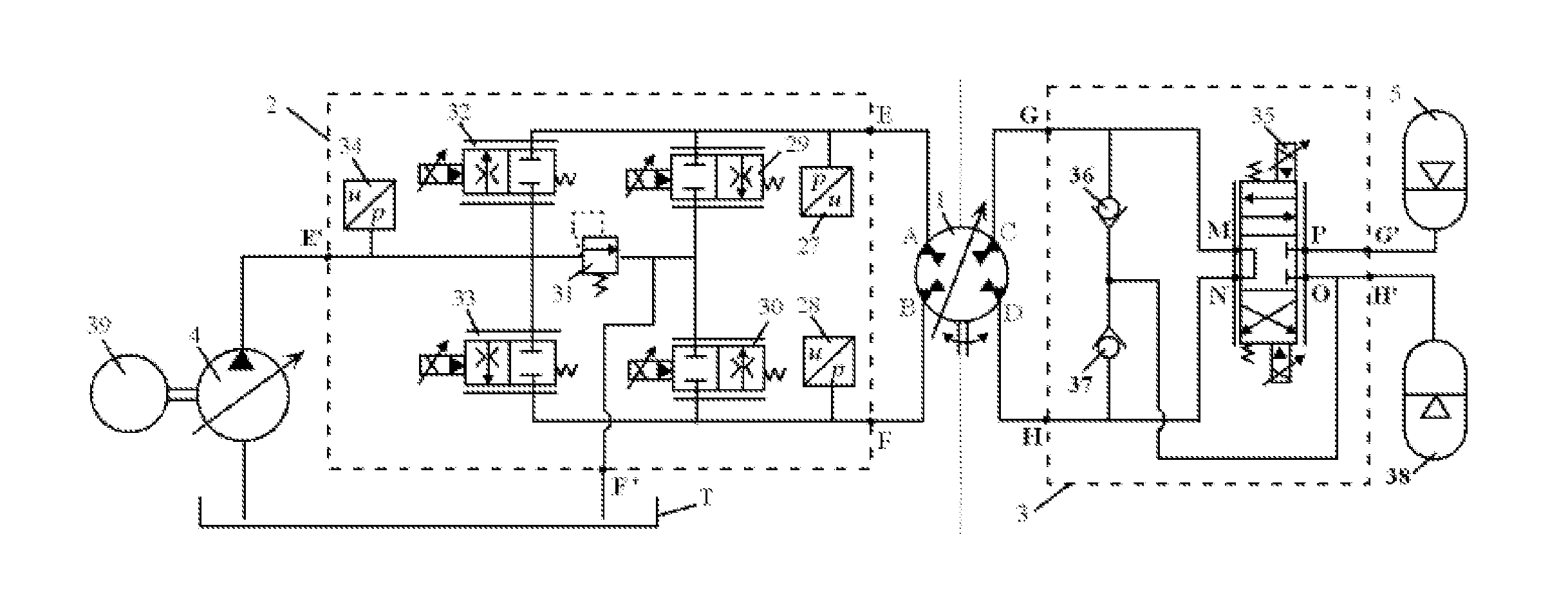
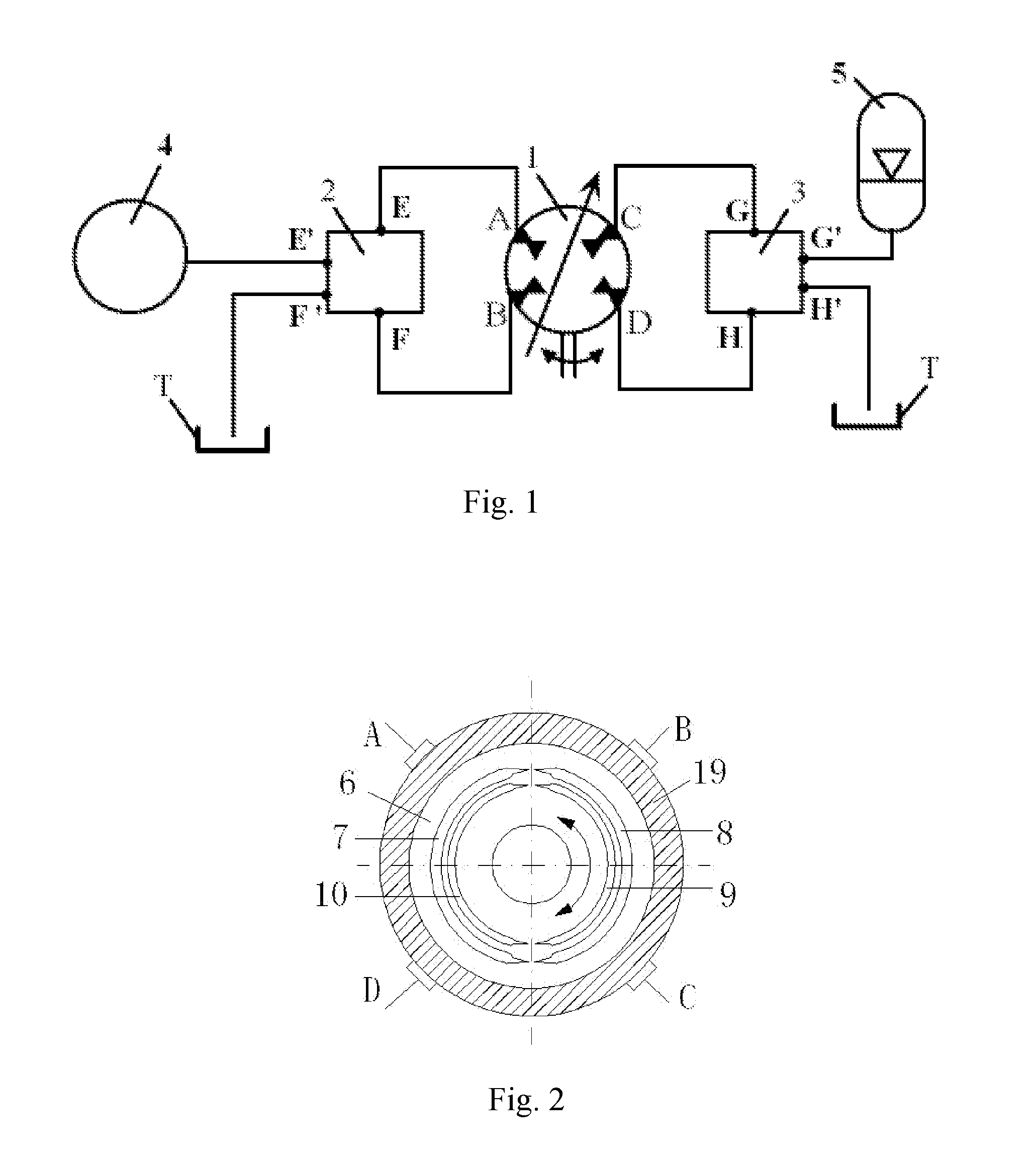
[0035]Referring to FIG. 4, according to the preferred embodiment 1, the positive control loop 2 of the double-loop control system with one hydraulic motor is the open loop with the separate meter-in and separate meter-out control system; the negative control loop 3 is the open loop controlled by the proportional direction valve; wherein the positive control loop 2 comprises a first pressure sensor 27, a second pressure sensor 28, a third pressure sensor 34, a first two-position two-way proportional throttle valve 29, a second two-position two-way proportional throttle valve 30, a third two-position two-way proportional throttle valve 32, a fourth two-position two-way proportional throttle valve 33, and a first relief valve 31; wherein the negative control loop 3 comprises a first check valve 36, a second check valve 37 and an electromagnetic proportional direction valve 35;

[0036]wherein the first working oil port E of the positive control loop 2 connects with t...

embodiment 2

Preferred Embodiment 2

[0040]Referring to FIG. 5, according to the preferred embodiment 2, the positive control loop 2 of the double-loop control system with the single hydraulic motor is a closed loop controlled by the hydraulic pump 4; the negative control loop 3 is an open loop controlled by the proportional direction valve; wherein the positive control loop 2 comprises a first relief valve 31, a second relief valve 41, a third relief valve 42, a first check valve 36, a second check valve 37, a fifth two-position two-way proportional throttle valve 44, and a slippage pump 43; wherein the negative control loop 3 comprises an electromagnetic proportional direction valve 35; a hydraulic pump 4 is a two-way displacement-variable pump driven by a power source 39, wherein the power source is an internal-combustion engine or a motor with a constant rotation rate;

[0041]wherein the first working oil port E of the positive control loop 2 connects with the first oil door A of the hydraulic m...

embodiment 3

Preferred Embodiment 3

[0045]Referring to FIG. 6, the hydraulic pump 4 is a constant hydraulic pump, the power source 39 is a speed variable motor, wherein the motor can be an AC induction motor, an AC or DC servo motor, or a switched reluctance motor, etc., with a rotation speed controller.

[0046]According to the double-loop control system with the single hydraulic motor of the preferred embodiment 3, the positive control loop 2 is a closed loop controlled by the hydraulic pump 4, which is the same as that of the preferred embodiment 2; the negative control loop 3 is an open loop with separate meter-in and separate meter-out control system, which is the same as that of the preferred embodiment 1.

[0047]Connections between the positive control loop 2 and the hydraulic motor 1 are the same as that of the preferred embodiment 2; the third working oil port G and the fourth working oil port H of the negative control loop 3 respectively connect with the third oil port C and the fourth oil p...


PUM


Abstract

A double-loop control system with a single hydraulic motor relates to a technical field of hydraulic transmission control, including a hydraulic motor (1), a positive control loop (2), a negative control loop (3), a hydraulic pump (4), an accumulator (5), and an oil tank, wherein the hydraulic motor (1) adopts a unique thrust structure with four inlet / outlet ports; the positive control loop (2) and the negative control loop (3) independently control the hydraulic motor (1), wherein the positive control loop (2) and the negative control loop (3) drive together or only one drives; or braking kinetic energy and potential energy of loads are stored in the accumulator (5) for energy recovery. The present invention uses only one hydraulic motor for satisfying different work conditions and different load driving requirements with advantages such as simple structure, high system reliability and high energy efficiency.

Description

CROSS REFERENCE OF RELATED APPLICATION[0001]This is a U.S. National Stage under 35 U.S.C 371 of the International Application PCT / CN2014 / 087288, filed Sep. 24, 2014, which claims priority under 35 U.S.C. 119(a-d) to CN 201410045978.X, filed Feb. 10, 2014.BACKGROUND OF THE PRESENT INVENTION[0002]1. Field of Invention[0003]The present invention relates to technical field of hydraulic transmission control, and more particularly to a double-loop control system with a single hydraulic motor.[0004]2. Description of Related Arts[0005]As a rotating actuator, a hydraulic motor mainly drives machines for rotating, lifting and traveling. In real application, due to a relatively large inertia of a driven load, a large output torque is often required during starting and accelerating; during stably operating, much less torque is required; and during braking, a large barking torque is needed. Therefore, system pressure and displacement must be determined to select a hydraulic motor according to a ...

Claims


Application Information

Patent Timeline
Patent Type & Authority Applications(United States)
IPC IPC(8): F15B1/02F15B11/04F16H61/02F15B13/04F16H61/00F15B11/08F15B13/044
CPCF15B1/024F16H2061/0034F15B11/04F15B13/044F15B13/0401F16H61/0025F16H61/0267F15B2013/041F15B2211/20538F15B2211/20546F15B2211/265F15B2211/625F15B2211/7051F15B2211/7058F15B11/08B60K6/12E02F9/128E02F9/2217E02F9/2289E02F9/2296F15B21/14F15B2211/20515F15B2211/20523F15B2211/20561F15B2211/212F15B2211/30575F15B2211/3058F15B2211/6309F15B2211/6313F15B2211/761F15B2211/88F16H61/40F16H61/4096F16H61/448Y02T10/62F15B2211/214F16H61/00
Inventor QUAN, LONGGAO, YOUSHANHAO, HUIMINHUANG, JIAHAIYANG, JING
Owner TAIYUAN UNIV OF TECH
Why Eureka
Try Eureka