Wafer coating system and method of manufacturing chip package

Active Publication Date: 2016-10-20
XINTEC INC
View PDF1 Cites 2 Cited by
  • Summary
  • Abstract
  • Description
  • Claims
  • Application Information

AI Technical Summary

Benefits of technology

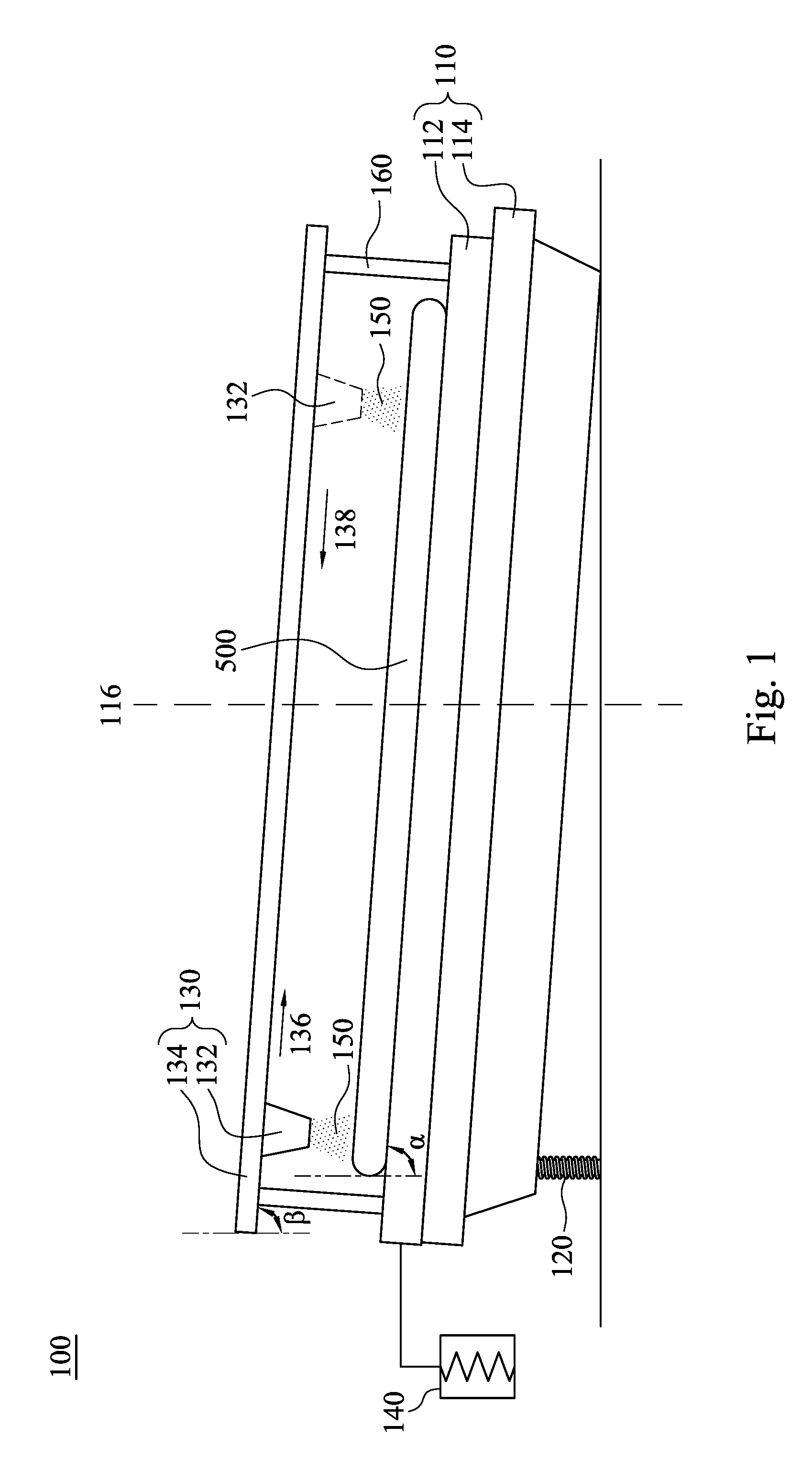
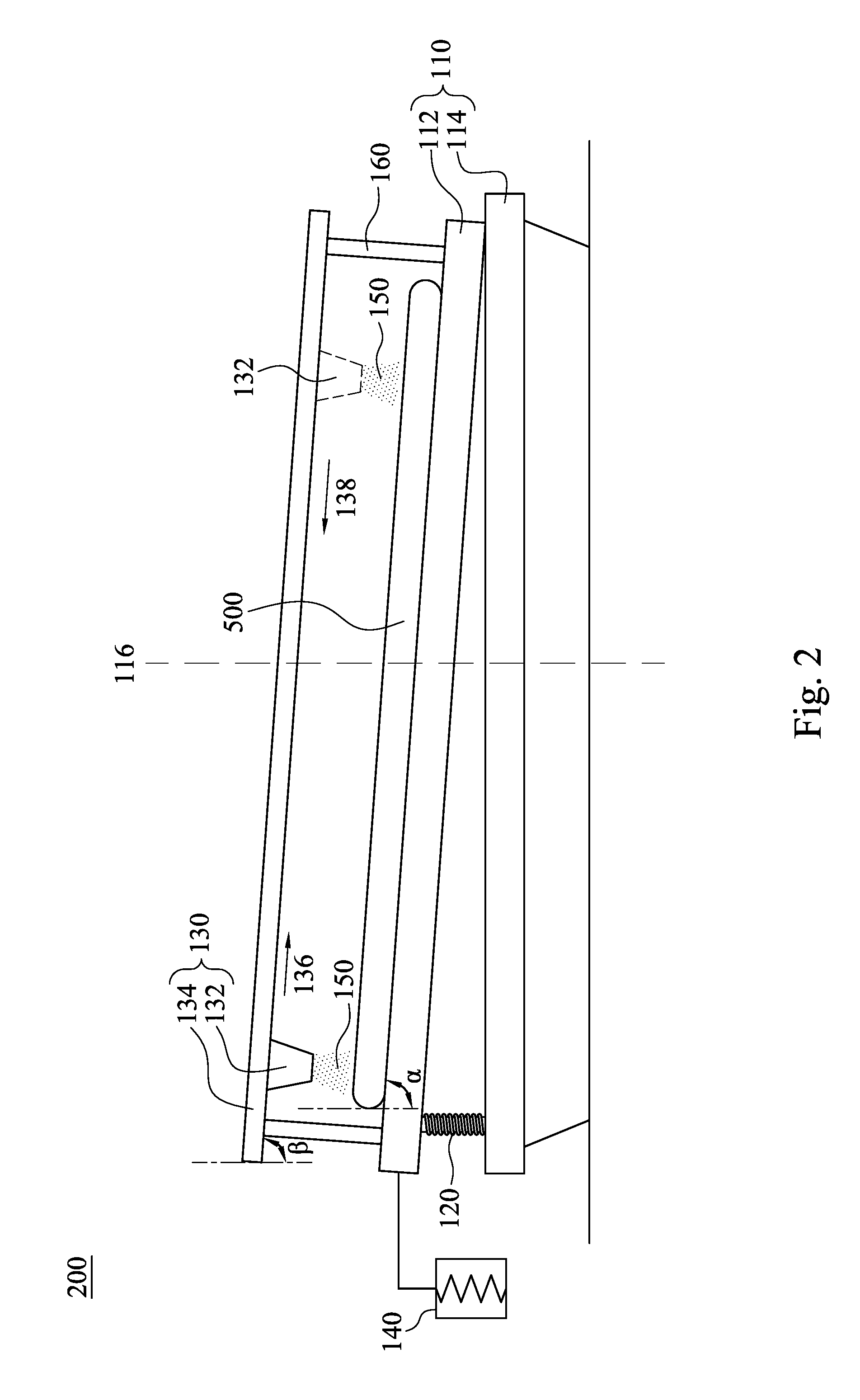
The present disclosure provides a wafer coating system and a method of fabricating a chip package using the system. The system includes a wafer chuck, a flowing insulating material sprayer, and a wafer tilting lifting pin. The wafer chuck has a carrier part and a rotating part, and the rotating part is designed to rotate with a predetermined axis. The flowing insulating material sprayer is positioned above the wafer chuck and includes a nozzle and a nozzle moving unit to spray the material on the wafer. The wafer is tilted to form a first acute angle between the wafer and direction of gravity. The method involves receiving a wafer, forming a through hole to expose the conductive pad, rotating the wafer, spraying the flowing insulating material, curing the material, and optionally removing a portion of the material to expose the conductive pad and form an opening for external connection. The system and method provide a uniform isolation layer and improved chip package fabrication.

Problems solved by technology

Therefore, it is more difficult and challenging to fabricate a semiconductor chip package in the subsequent process for the semiconductor chip.
Generally, an oxide is used to prepare an isolation layer of the chip, but the oxide is expensive, and the process of depositing the oxide is complicated and time-consuming, and thus decreases efficiency of the process.
However, the epoxy material is easily affected by the gravity to aggregate, which is not benefit for forming uniform isolation layer, and thus decreases the yield of the chip package.

Method used


Image

  • Wafer coating system and method of manufacturing chip package
  • Wafer coating system and method of manufacturing chip package
  • Wafer coating system and method of manufacturing chip package

Examples


Embodiment Construction

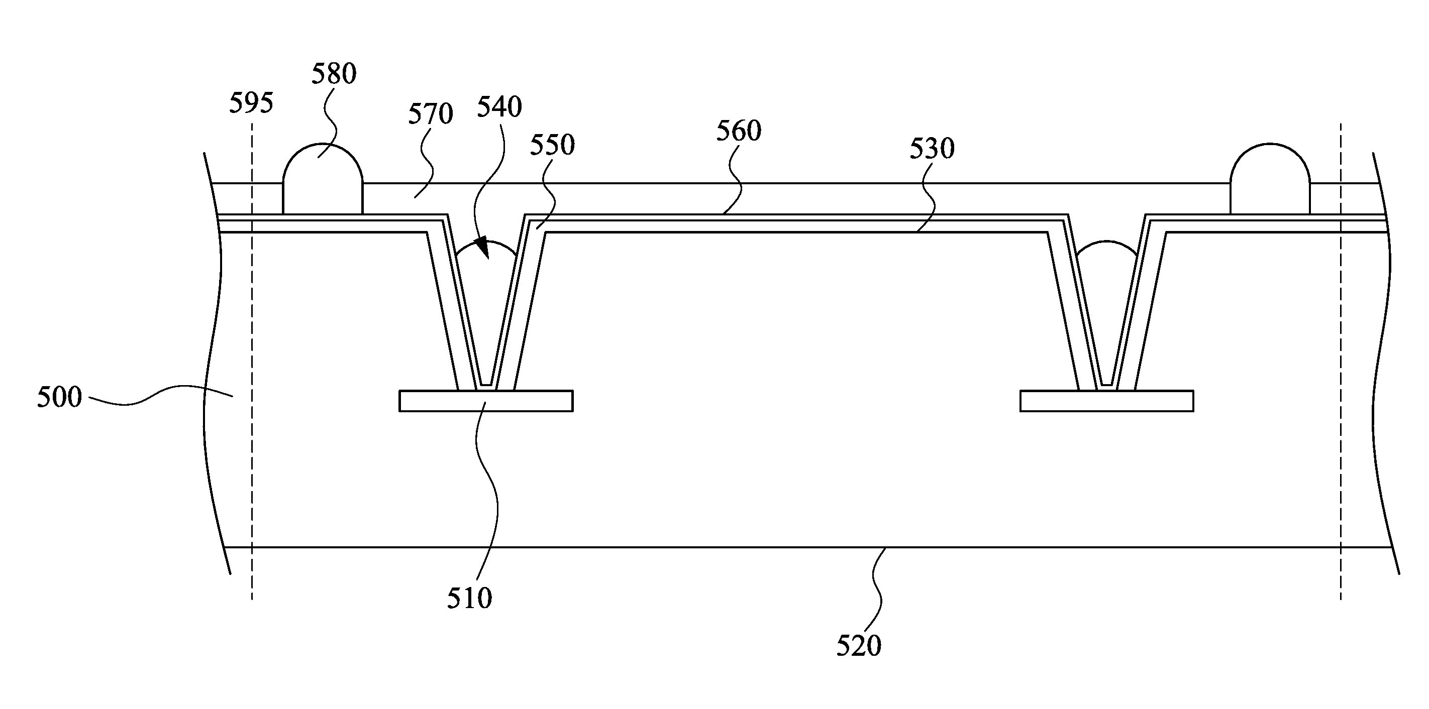
[0042]The following disclosure provides many different embodiments, or examples, for implementing different features of the provided subject matter. Specific examples of components and arrangements are described below to simplify the present disclosure. These are, of course, merely examples and are not intended to be limiting. For example, the formation of a first feature over or on a second feature in the description that follows may include embodiments in which the first and second features are formed in direct contact, and may also include embodiments in which additional features may be formed between the first and second features, such that the first and second features may not be in direct contact. In addition, the present disclosure may repeat reference numerals and / or letters in the various examples. This repetition is for the purpose of simplicity and clarity and does not in itself dictate a relationship between the various embodiments and / or configurations discussed.

[0043]R...


PUM


Abstract

A wafer coating system includes a wafer chuck, a flowing insulating material sprayer and a wafer tilting lifting pin. The wafer chuck has a carrier part and a rotating part, which the carrier part is mounted on the rotating part to carry a wafer, and the rotating part is configured to rotate with a predetermined axis. The flowing insulating material sprayer is above the wafer chuck and configured to spray a flowing insulating material to the wafer, and the wafer tilting lifting pin is configured to form a first acute angle between the wafer and direction of gravity.

Description

RELATED APPLICATIONS[0001]This application claims priority to U.S. provisional Application Ser. No. 62 / 150,255, filed Apr. 20, 2015, which is herein incorporated by reference.BACKGROUND[0002]1. Field of Invention[0003]The present invention relates to a wafer coating system and a method of manufacturing a chip package using the wafer coating system.[0004]2. Description of Related Art[0005]Along with the trends of electronic devices toward lighter and more compact, the semiconductor chip corresponding to the electronic device has a reduced size and increased wiring density. Therefore, it is more difficult and challenging to fabricate a semiconductor chip package in the subsequent process for the semiconductor chip. Wafer-level chip package is a method of packaging the semiconductor chip, which the method means all the chips are packaged and tested after completion of manufacturing these chips on the wafer, and then the wafer is cut into single chip packages.[0006]Since the size of the...

Claims


Application Information

Patent Timeline
IPC IPC(8): H01L21/56H01L21/67B05B1/24H01L21/78H01L23/29H01L23/00H01L21/687H01L21/768
CPCH01L21/561H01L21/68742H01L21/68785H01L21/67109H01L21/67126H01L2224/13022H01L21/78H01L23/293H01L24/11B05B1/24H01L2224/12105H01L21/76898H01L21/56H01L21/6715H01L21/68764H01L23/3192H01L24/03H01L24/94H01L2224/02313H01L2224/0346H01L2224/0391H01L2224/05022H01L2224/05548H01L2224/05573H01L2224/05624H01L2224/05647H01L2224/05655H01L2224/13024H01L2224/94H01L21/76831H01L2224/0401H01L2224/131H01L21/02118H01L21/02282H01L2924/00014H01L2224/03H01L2224/11H01L2924/014
Inventor CHEN, YU-TUNGSU, QUAN-QUNSHIU, CHUAN-JINCHEN, CHIEN-HUIYEH, HSIAO-LANHO, YEN-SHIH
Owner XINTEC INC
Why Eureka
Try Eureka