Magnesium-sulfur secondary battery containing a metal polysulfide-preloaded active cathode layer

a secondary battery and magnesium-sulfur technology, applied in the field of rechargeable magnesium-sulfur cells, to achieve the effect of maximizing both the energy density and power density of the battery cell, high sulfur loading, and high metal polysulfide loading

Active Publication Date: 2016-10-20
GLOBAL GRAPHENE GRP INC
View PDF5 Cites 33 Cited by
  • Summary
  • Abstract
  • Description
  • Claims
  • Application Information

AI Technical Summary

Benefits of technology

[0034]It may be noted that magnesium organohaloaluminate electrolytes, generated in situ from the reaction between a Lewis acid and a Lewis base, are nucleophilic and, in prior art teaching, would be considered un-suitable for use in a Mg—S cell. For example, a 2:1 mixture of phenylmagnesium chloride and aluminum trichloride (AlCl3) in tetrahydrofuran (THF) would be incompatible with an electrophilic sulfur cathode. Quite unexpectedly, the implementation of the presently invented active cathode layer enables this class of electrolytes to work reasonably well in the Mg—S cells. This is a great accomplishment by itself.
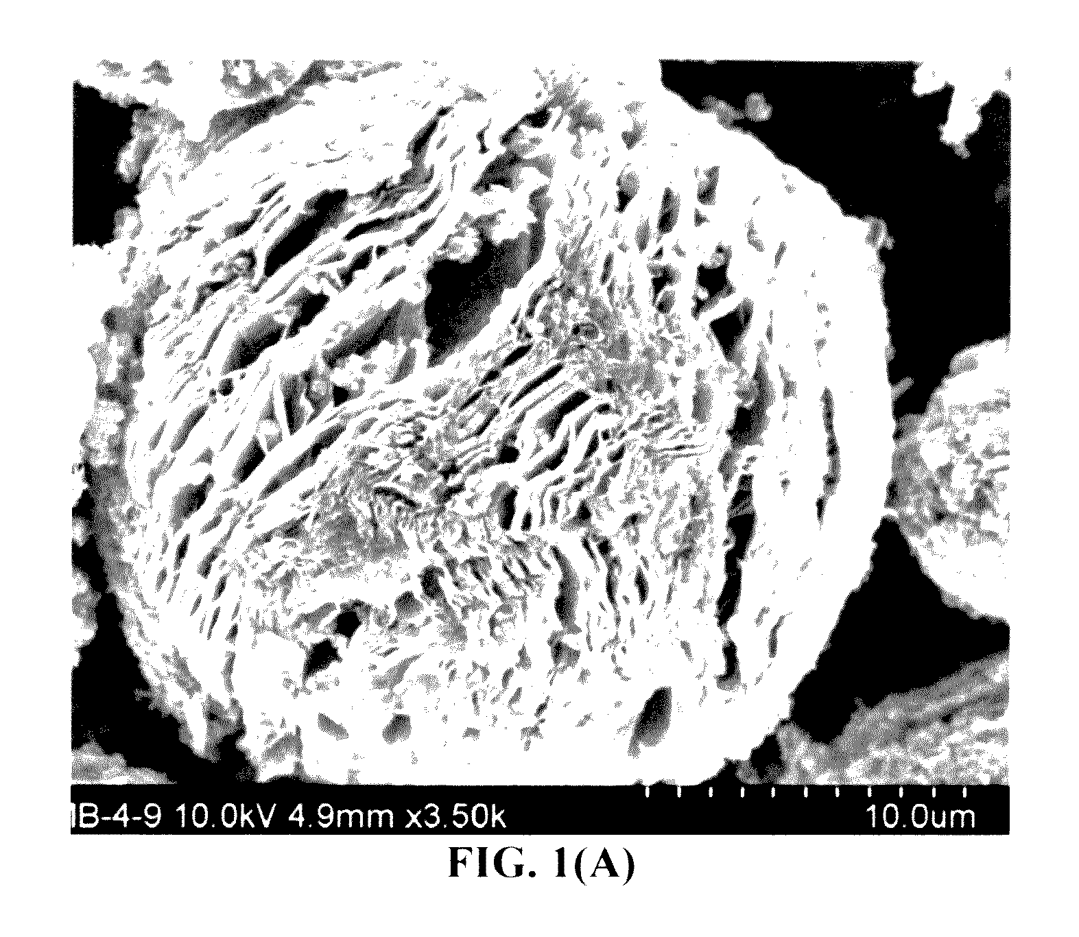
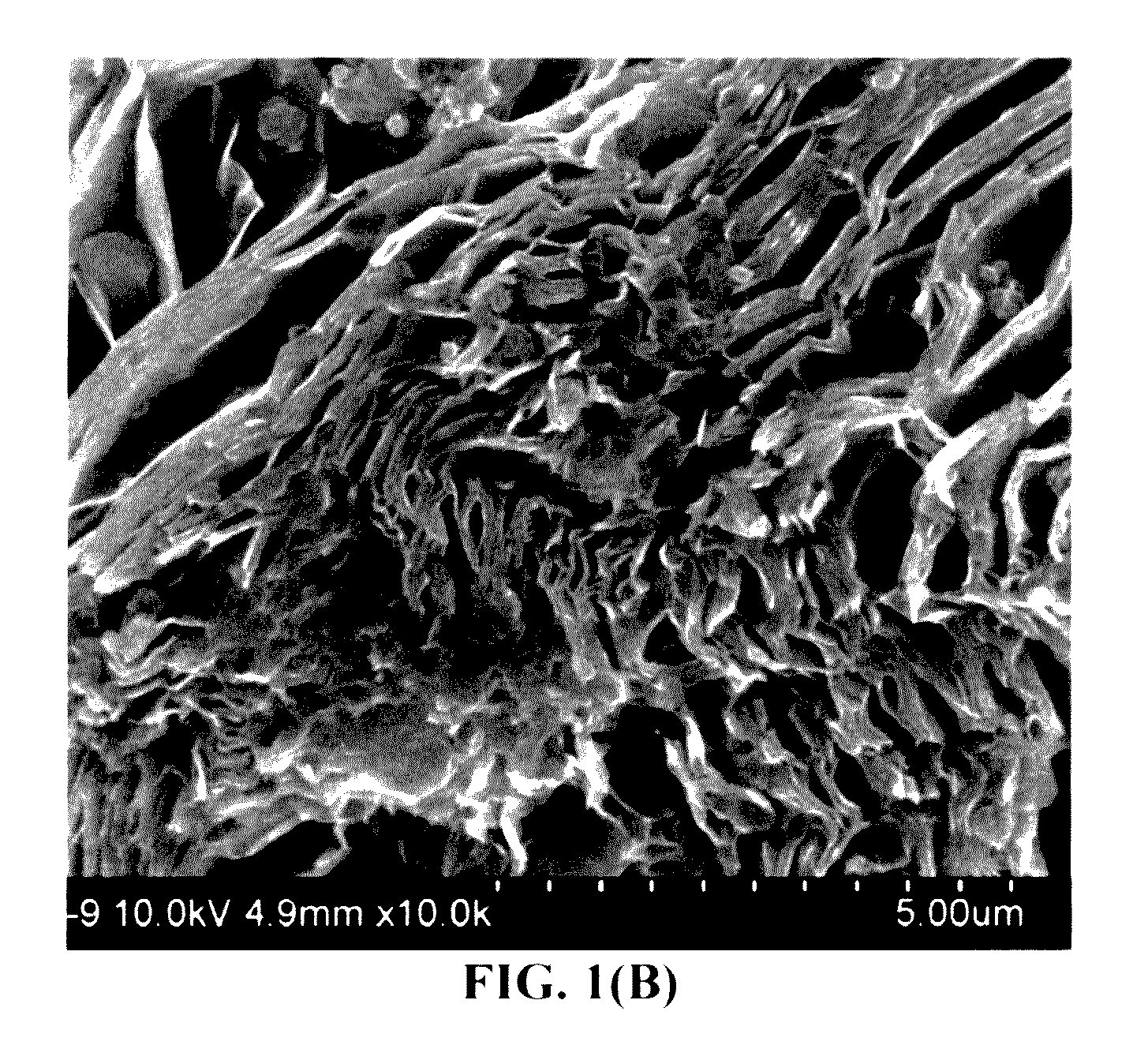
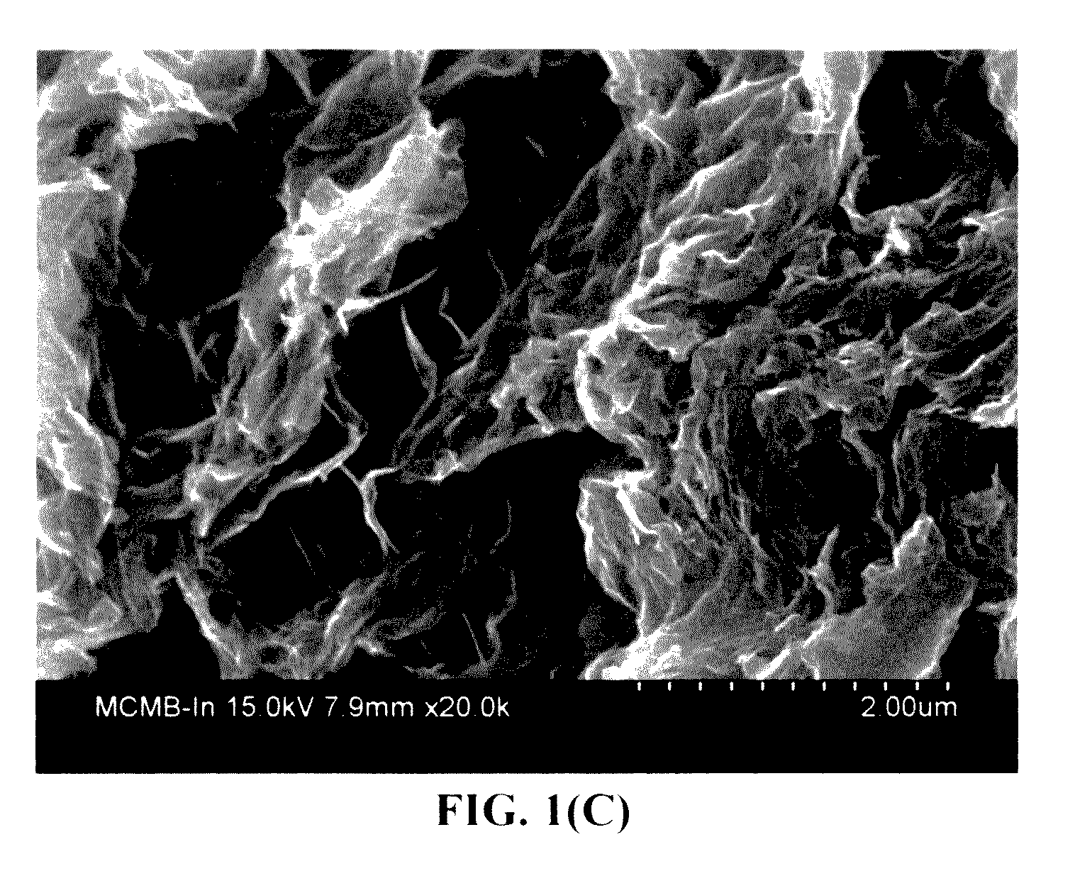
[0036]A special and highly advantageous feature of the inventive preloaded cathode layer is the notion that this class of metal sulfide species can be dissolved in a solvent to form a uniform solution. This solution readily permeates into the pores of the porous structure and the metal sulfide, when precipitated from the solution, can deposit uniformly in the form of a thin coating (preferably <20 nm in thickness) or ultra-fine particles (preferably <20 nm in diameter) in the pores or on the massive surfaces. This approach enables the deposition of a large amount of metal polysulfide relative to the porous structure material (hence, achieving a high proportion of cathode active material). This is quite surprising since pure sulfur could not be uniformly deposited into a porous structure using a solution deposition process to achieve both high sulfur amount and ultra-thin coating or small particles (<20 nm). This simple solution deposition process for metal polysulfide (not for sulfur) has another advantage in that it does not require a chemical reaction or electrochemical reaction (prior to battery fabrication), which otherwise can be more difficult to control, more tedious, and more expensive.
[0038]It is highly advantageous to achieve a high metal polysulfide loading (hence, high sulfur loading) and yet, concurrently, form an ultra-thin coating or ultra-small diameter particles of metal polysulfide (hence, sulfur) in terms of maximizing both the energy density and power density of a battery cell. This has not been possible with any prior art sulfur or polysulfide loading techniques. For instance, we have been able to deposit nano-scaled polysulfide particles or coating that occupy a >90% weight fraction of the cathode layer and yet maintain a coating thickness or particle diameter <3 nm. This is quite a feat in the art of any metal-sulfur batteries. In another example, we have achieved a >95% S loading at an average polysulfide coating thickness of 4.8-7 nm. These ultra-thin dimensions (3-7 nm) enable facile cathode reactions and nearly perfect sulfur utilization efficiency, something that no prior worker has been able to achieve.
[0039]The strategy of pre-loading metal polysulfide, instead of pure sulfur itself, in the cathode prior to the battery cell fabrication has a highly unexpected yet major advantage. We have surprisingly observed that such a strategy leads to a metal-sulfur battery with a longer cycle life. Not wishing to be limited by theory, but we think that this might be due to the notion that sulfur can undergo large-scale volume expansion when the battery is discharged. On repeated charges / discharges, the cathode structure can be easily damaged if an excessively high amount of sulfur is loaded into the cathode. If instead a metal polysulfide is preloaded, the volume changes only occur to a much smaller extent, effectively alleviating this cathode structure damage problem.

Problems solved by technology

However, the current Li-sulfur cells reported by industry leaders in sulfur cathode technology have a maximum cell specific energy of 250-400 Wh / kg (based on the total cell weight), which is far below what is possible.
Despite its considerable advantages, the Li—S cell is plagued with several major technical problems that have thus far hindered its widespread commercialization:(1) Lithium metal cells still have dendrite formation and related internal shorting issues.(2) Sulfur or sulfur-containing organic compounds are highly insulating, both electrically and ionically.
Various carbon-sulfur composites have been utilized for this purpose, but only with limited success owing to the limited scale of the contact area.
This is mainly due to the high solubility of the lithium polysulfide anions formed as reaction intermediates during both discharge and charge processes in the polar organic solvents used in electrolytes.
In addition, the solid product that precipitates on the surface of the positive electrode during discharge becomes electrochemically irreversible, which also contributes to active mass loss.(4) More generally speaking, a significant drawback with cells containing cathodes comprising elemental sulfur, organosulfur and carbon-sulfur materials relates to the dissolution and excessive out-diffusion of soluble sulfides, polysulfides, organo-sulfides, carbon-sulfides and / or carbon-polysulfides (hereinafter referred to as anionic reduction products) from the cathode into the rest of the cell.
This process leads to several problems: high self-discharge rates, loss of cathode capacity, corrosion of current collectors and electrical leads leading to loss of electrical contact with active cell components, fouling of the anode surface, and clogging of the pores in the cell membrane separator which leads to loss of ion transport and large increases in internal resistance in the cell.
Some interesting cathode developments have been reported recently to contain lithium polysulfides; but, their performance still fall short of what is required for practical applications.
However, the fabrication of the proposed highly ordered meso-porous carbon structure requires a tedious and expensive template-assisted process.
It is also challenging to load a large proportion of sulfur into these meso-scaled pores using a physical vapor deposition or solution precipitation process.
But, this method is incapable of creating a large proportion of S particles on GO surfaces (i.e. typically <66% of S in the GO-S nanocomposite composition).
It may be noted that the highest achievable specific capacity of 1,100 mAh / g represents a sulfur utilization efficiency of only 1,100 / 1,675=65.7% even at such a low charge / discharge rate (0.02 C means completing the charge or discharge process in 1 / 0.02=50 hours; 1 C=1 hour, 2 C=½ hours, and 3 C=⅓ hours, etc.) Further, such a S-GO nanocomposite cathode-based Li—S cell exhibits very poor cycle life, with the capacity typically dropping to less than 60% of its original capacity in less than 40 charge / discharge cycles.
Such a short cycle life makes this Li—S cell not useful for any practical application.
Unfortunately, this method does not appear to be capable of producing S particles less than 40 nm.
The resulting Li—S cell exhibits very poor cycle life (a 50% decay in capacity after only 50 cycles).
Again, this implies that a large proportion of S did not contribute to the lithium storage, resulting in a low S utilization efficiency.
These S particles prevent graphene sheets from contacting each other, making it impossible for otherwise conducting graphene sheets to form a 3-D network of electron-conducting paths in the cathode.
This unintended and unexpected outcome is another reason why these prior art Li—S cells have performed so poorly.
Unfortunately, in general, the cathode active materials capable of storing Mg ions exhibit even lower specific capacity (typically <200 mAh / g and more typically <150 mAh / g) as compared to the current cathode active materials for lithium-ion cells.
However, the Mg—S cell is not without a problem.
In fact, the Mg—S cell has even more problems than the Li—S cell does.
There are some similar issues between Mg—S and Li—S batteries, such as: (i) low active material utilization rate, (ii) poor cycle life, and (iii) low Coulombic efficiency.
Again, these drawbacks arise mainly from insulating nature of S, dissolution of S and metal polysulfide intermediates in liquid electrolytes (and related Shuttle effect), and large volume change during battery charging / discharging.
However, there are very serious issues that are unique to Mg—S batteries that Li—S batteries do not have: (a) The Li metal at the anode of the Li—S cell can form a passivating layer that is permeable to Li+ ions, but the passivating layer on the Mg metal at the anode of the Mg—S cell is not permeable to the Mg2+ ions, making the dissolution / re-plating of Mg2+ ions (discharge / re-charge of the Mg metal secondary battery) difficult or impossible in most of the known electrolytes; (b) Due to this reason, there are only a limited number of electrolytes that are compatible with Mg metal at the anode; and (c) Unfortunately, these electrolytes are nucleophilic, making them incompatible with the electrophilic sulfur cathode, which is known to require a non-nucleophilic electrolyte.
Unfortunately, a large proportion of non-active materials (such as conductive additive and binder that are not capable of storing metal ions) is typically used in their Li—S cells.

Method used


Image

  • Magnesium-sulfur secondary battery containing a metal polysulfide-preloaded active cathode layer
  • Magnesium-sulfur secondary battery containing a metal polysulfide-preloaded active cathode layer
  • Magnesium-sulfur secondary battery containing a metal polysulfide-preloaded active cathode layer

Examples


example 1

Meso-porous Soft Carbon as a Supporting and Protective Backbone for Metal Polysulfide

[0146]Chemically etched or expanded soft carbon was prepared from heat-treating a liquid crystalline aromatic resin (50 / 50 mixture of anthracene and pyrene) at 200° C. for 1 hour. The resin was ground with a mortar, and calcined at 900° C. for 2 h in a N2 atmosphere to prepare the graphitizable carbon or soft carbon. The resulting soft carbon was mixed with small tablets of KOH (four-fold weight) in an alumina melting pot. Subsequently, the soft carbon containing KOH was heated at 750° C. for 2 h in N2. Upon cooling, the alkali-rich residual carbon was washed with hot water until the outlet water reached a pH value of 7. The resulting chemically etched or expanded soft carbon was dried by heating at 60° C. in a vacuum for 24 hours. This material can be used in both the anode and cathode due to its high specific surface area and its ability to capture and store Mg atoms on its surfaces. These surface...

example 2

Expanded “Activated Carbon” (E-AC) as a Supporting and Protective Porous Backbone for Metal Polysulfide

[0147]Activated carbon (AC, from Ashbury Carbon Co.) was treated with an acid solution (sulfuric acid, nitric acid, and potassium permanganate at a ratio of 4:1:0.05) for 24 hours. Upon completion of the reaction, the mixture was poured into deionized water and filtered. The treated AC was repeatedly washed in a 5% solution of HCl to remove most of the sulphate ions. The sample was then washed repeatedly with deionized water until the pH of the filtrate was neutral. The slurry was then dried in a vacuum oven pre-set at 70° C. for 24 hours. The dried sample was then placed in a tube furnace at 1,050° C. for 2 minutes to obtain expanded AC. This material can be used in both the anode and cathode of a Mg cell due to its high specific surface area and ability to capture and store Mg and / or S atoms on its surfaces. These surfaces were also found to be particularly suitable for supportin...

example 3

Chemically Treated (Expanded) Needle Coke as a Supporting and Protective Porous Backbone for Metal Polysulfide

[0148]Anisotropic needle coke has a fully developed needle-shape texture of optical anisotropy. Volatile species of the raw coke was estimated to be around 5 wt. %. Activation was carried out using KOH in a reaction apparatus that consisted of a stainless steel tube and a nickel sample holder. KOH activation was carried out at 800° C. for 2 h under Ar flow. The coke / KOH ratio was varied between 1 / 1 and 1 / 4. Upon cooling, the alkali-rich coke was washed with hot water until the outlet water reached a pH value of 7. The resulting chemically etched or expanded coke was dried by heating at 60° C. in a vacuum for 24 hours. The treated coke is highly porous, having a pore size range of approximately 1-85 nm and being suitable for entry of metal polysulfide solution and deposition of metal polysulfide.


PUM

PropertyMeasurementUnit
sizeaaaaaaaaaa
specific surface areaaaaaaaaaaa
weight fractionaaaaaaaaaa

Abstract

A rechargeable magnesium-sulfur cell comprising an anode layer, an electrolyte, a metal polysulfide-preloaded active cathode layer, wherein the active cathode layer comprises: (a) an integral porous structure having massive surfaces (specific surface area >100 m2 / g) or pores with a size from 1.0 nm to 100 nm and wherein multiple particles; and (b) a metal polysulfide, MxSy, preloaded in the pores or deposited on the massive surfaces, wherein x is an integer from 1 to 3 and y is an integer from 1 to 10, and M is a metal element selected from an alkali metal, an alkaline metal, a transition metal, a metal from groups 13 to 17 of the periodic table, or a combination thereof. The metal polysulfide is in a form of solid-state thin coating or small particles with a thickness or diameter less than 50 nm.

Description

FIELD OF THE INVENTION[0001]The present invention is directed at a rechargeable magnesium-sulfur cell, also referred to as the Mg—S secondary cell.BACKGROUND[0002]With the rapid development of hybrid (HEY), plug-in hybrid electric vehicles (HEV), and all-battery electric vehicles (EV), there is an urgent need for a rechargeable battery having a high specific energy, high energy density, high rate capability, long cycle life, and safety. One of the most promising energy storage devices is the lithium-sulfur (Li—S) cell since the theoretical capacity of Li is 3,861 mAh / g and that of S is 1,675 mAh / g. In its simplest form, a Li—S cell consists of elemental sulfur as the positive electrode and lithium as the negative electrode active materials. The lithium-sulfur cell operates with a redox couple, described by the reaction S8+16Li8Li2S that lies near 2.2 V with respect to Li+ / Li0. This electrochemical potential is approximately ⅔ of that exhibited by conventional positive electrodes (e....

Claims


Application Information

Patent Timeline
Patent Type & Authority Applications(United States)
IPC IPC(8): H01M4/58H01M10/0568H01M2/16H01M10/054H01M4/38H01M4/62
CPCH01M4/5815H01M4/38H01M4/625H01M4/622H01M2300/0037H01M10/054H01M10/0568H01M2220/20H01M2/1673H01M4/136H01M4/66H01M4/80H01M2004/021H01M2004/028H01M50/46Y02E60/10
Inventor HE, HUIZHAMU, ARUNAJANG, BOR Z
Owner GLOBAL GRAPHENE GRP INC
Why Eureka
Try Eureka