
Coil electronic component and method of manufacturing the same

Active Publication Date: 2016-10-20
SAMSUNG ELECTRO MECHANICS CO LTD
View PDF6 Cites 35 Cited by
  • Summary
  • Abstract
  • Description
  • Claims
  • Application Information

AI Technical Summary

Benefits of technology

The present invention provides a capacitor component that reduces acoustic noise when mounted on a printed circuit board.

Problems solved by technology

The vibrations may be transferred to a printed circuit board through an external electrode of the multilayer ceramic capacitor and a soldering material connecting the external electrode to the printed circuit board, and thus, the entire printed circuit board may become an acoustic reflective surface to generate the vibrated sound, which is observed as noise.
This vibrated sound may have a frequency corresponding to an audio frequency in a region of 20 to 20, 000 Hz, which may cause listener discomfort and is referred to as acoustic noise.
Furthermore, in recent electronic devices, since an attempt to reduce the noise of equipment components has been ongoing, acoustic noise generated in the multilayer ceramic capacitor as described above may become more prominent.
In addition, in devices having a voice circuit, acoustic noise may overlap with audio output, thereby leading to deterioration in the quality of the device.

Method used


Image

  • Coil electronic component and method of manufacturing the same
  • Coil electronic component and method of manufacturing the same
  • Coil electronic component and method of manufacturing the same

Examples


Embodiment Construction

[0033]Hereinafter, embodiments of the present inventive concept will be described as follows with reference to the attached drawings.

[0034]The present inventive concept may, however, be exemplified in many different forms and should not be construed as being limited to the specific embodiments set forth herein. Rather, these embodiments are provided so that this disclosure will be thorough and complete, and will fully convey the scope of the disclosure to those skilled in the art.

[0035]Throughout the specification, it will be understood that when an element, such as a layer, region or wafer (substrate), is referred to as being “on,”“connected to,” or “coupled to” another element, it can be directly “on,”“connected to,” or “coupled to” the other element or other elements intervening therebetween maybe present. In contrast, when an element is referred to as being “directly on, ”“directly connected to,” or “directly coupled to” another element, there may be no elements or layers interv...


PUM

PropertyMeasurementUnit
Lengthaaaaaaaaaa
Electrical conductoraaaaaaaaaa
Widthaaaaaaaaaa

Abstract

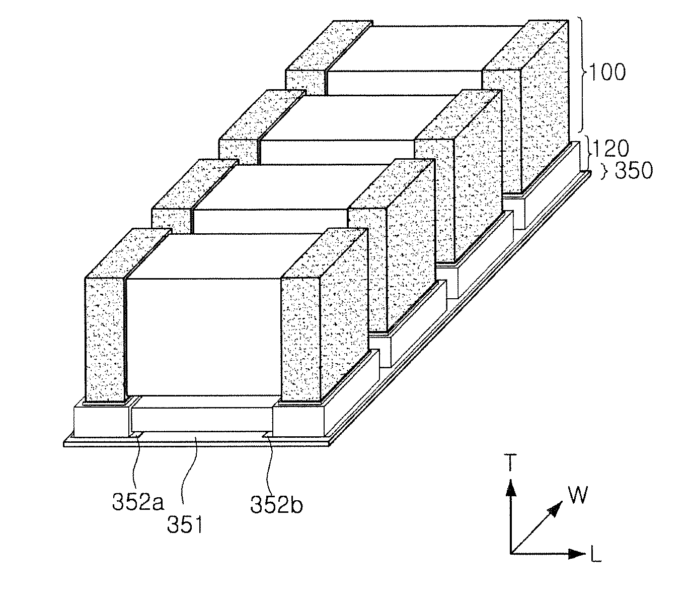
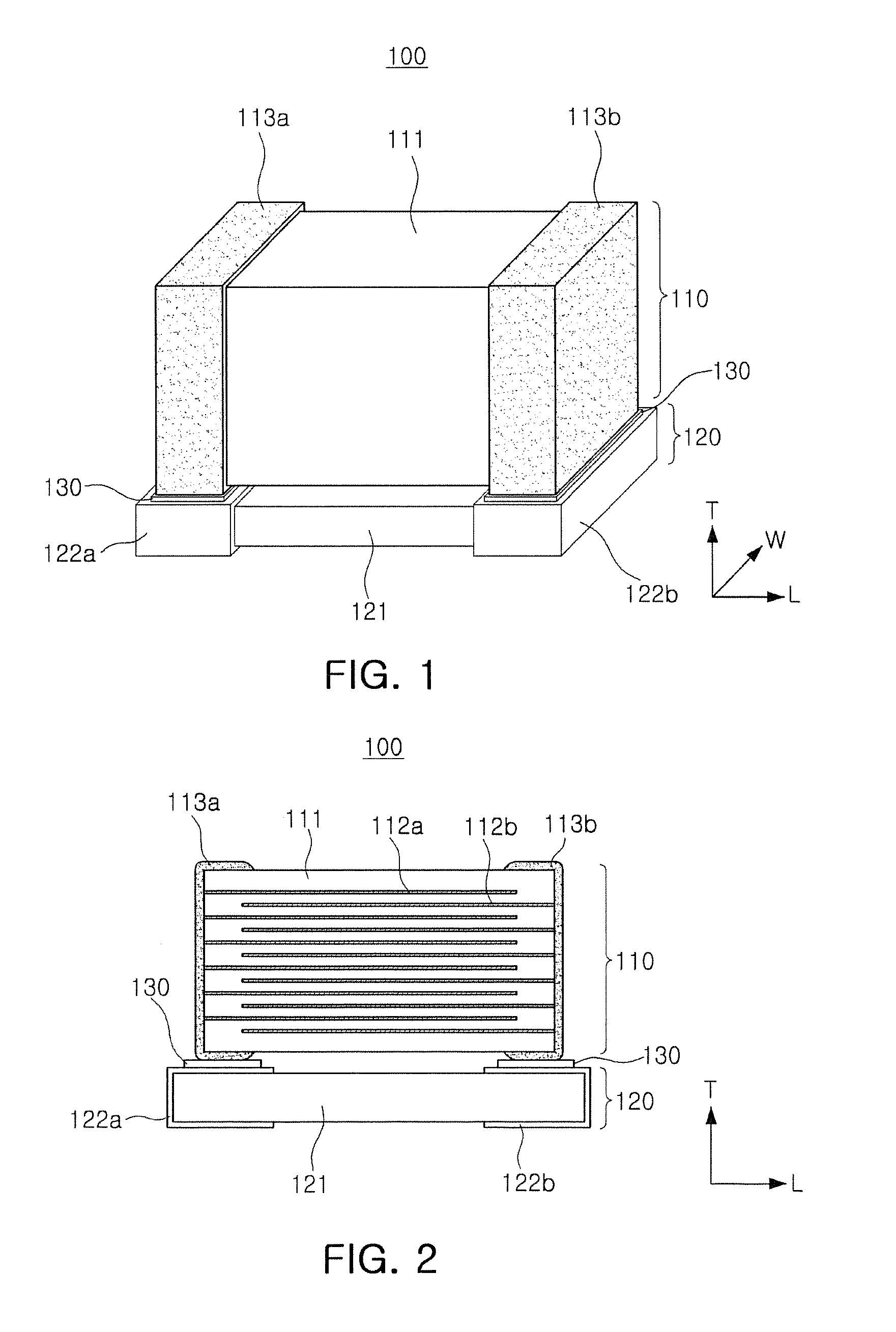
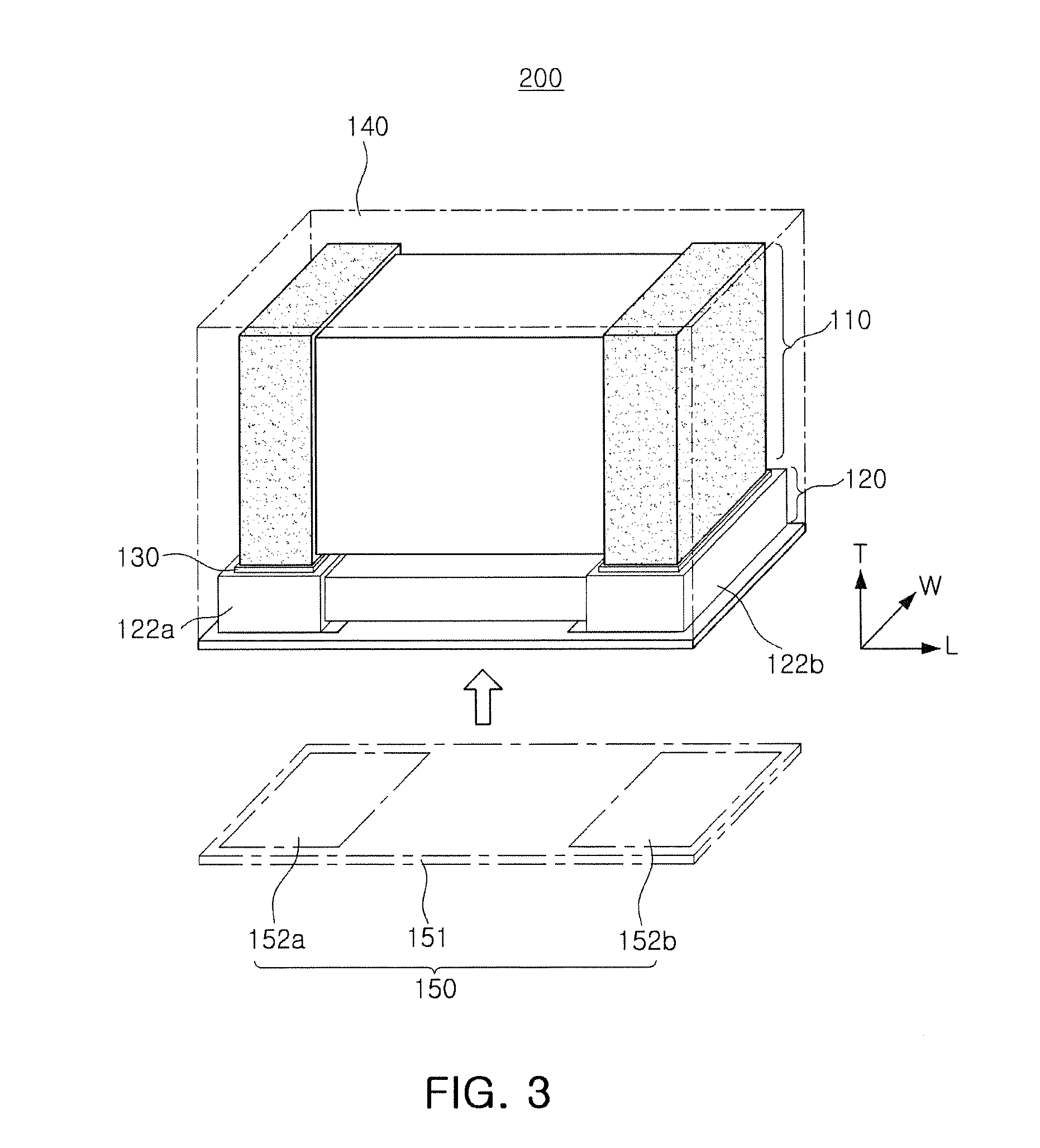
A capacitor component includes a capacitor including a plurality of internal electrodes, a capacitor body containing a piezoelectric material disposed in at least regions between the plurality of internal electrodes, and external electrodes connected to the plurality of internal electrodes; and an interposer disposed to be coupled to the capacitor and including a buffer substrate containing a buffer material having a degree of piezoelectricity lower than that of the piezoelectric material, and connection electrodes electrically connected to the external electrodes.

Description

CROSS-REFERENCE TO RELATED APPLICATIONS[0001]This application claims the benefit of priority to Korean Patent Application No. 10-2015-0055397, filed on Apr. 20, 2015 with the Korean Intellectual Property Office, the entirety of which is incorporated herein by reference.TECHNICAL FIELD[0002]The present inventive concept relates to a capacitor component.BACKGROUND[0003]Examples of electronic components using a ceramic material include capacitors, inductors, piezoelectric elements, varistors, thermistors, and the like.[0004]Among ceramic electronic components, multilayer ceramic capacitors (MLCC) may be used in various electronic devices, due to advantages such as compact size, high capacitance, ease of mounting, and the like.[0005]For example, a multilayer ceramic capacitor may be used in a chip type condenser mounted on a printed circuit board of several electronic products such as imaging devices, for example, liquid crystal displays (LCDs) or plasma display panels (PDPs), computers...

Claims


Application Information

Patent Timeline
IPC IPC(8): H05K1/02H05K1/18H01G4/30H01G4/248H01G4/12H01G4/012
CPCH05K1/0216H01G4/12H01G4/012H05K2201/10015H01G4/248H05K1/181H01G4/30H05K1/0306H05K1/141H05K2201/10378H05K2201/1053H05K2201/10962H01G4/38H01G2/06H01G4/232H10N30/88H10N30/50
Inventor PARK, HEUNG KIL
Owner SAMSUNG ELECTRO MECHANICS CO LTD
Learn More