Powered air breathing apparatus

a technology of air filtering device and air filtering chamber, which is applied in the direction of respirator, life-saving device, respiratory mask, etc., can solve the problems of increasing resistance through the filter life, fluctuation of flow rate, and maintaining a given flow rate across any combination of accessories, so as to reduce the battery life and the flow rate of battery powered respirators.

Active Publication Date: 2016-11-03
SCOTT HEALTH & SAFETY
View PDF3 Cites 3 Cited by
  • Summary
  • Abstract
  • Description
  • Claims
  • Application Information

AI Technical Summary

Benefits of technology

[0012]The apparatus and method in accordance with the invention has the advantage that by measuring pressure and using the differential to calculate the flow rate of gas through the apparatus, a much more accurate figure for the flow rate is obtained as compared with prior art systems without imposing a significant load on the air supply unit which would result in an increase in power requirements.
[0055]The reservoir may be a flexible container or may be collapsible. Furthermore, it may be connected directly to the outlet of the blower, directly to the intake of the mask, or in-line in the delivery hose. A one way valve is preferably provided on the outlet end of the reservoir to prevent flow of air from the mask back into the reservoir. This will prevent back pressurisation of the system which could still cause an increased load on the blower and also will prevent exhaled air, which will have a higher carbon dioxide content, from being fed back into the reservoir for re-breathing by the user.

Problems solved by technology

Modern respirators typically have a wide selection of accessories in the form of filter types, varying design of headtop or mask for different applications etc, and this gives rise to issues with maintaining a given flow rate across any combination of accessories.
The flow resistance of a particular filter can also vary through its life as airborne particles are drawn into and retained on the filter medium, interfering with the movement of air therethrough and thus constantly increasing resistance through the filter life.
Furthermore, the mere act of the user breathing causes variations in the load on the motor causing fluctuations in the flow rate.
On the other hand, as the user breathes out, air flow is inhibited, even when a non-return valve is used, thereby increasing the load on the motor
This approach also suffers from the drawback that it does not cater for changes resulting from variations in altitude (motor speed will increase as the density of the atmosphere decreases).
The added complication to all this is that as the resistance changes over the life of the filter, the load increases complicating the load and speed algorithm.
However, as a result of filters getting more technical for different contamination challenges, a desire to maintain a flow rate regardless of the initial filter resistance and variations in filter resistance through its operating life, and a desire for different headtops to suit different applications, these approximation methods are now becoming insufficient.
Furthermore, analysis of the air within a typical powered air breathing apparatus assembly has shown that turbulence exists in the respirator assembly at flow rates that are required for breathing.
This complicates any generally acceptable way of measuring airflow without the use of laminar air control system in place that causes a heavy load on the system either causing flow rates to be decreased and / or battery life of battery powered respirators to be reduced significantly.

Method used


Image

  • Powered air breathing apparatus
  • Powered air breathing apparatus
  • Powered air breathing apparatus

Examples


Embodiment Construction

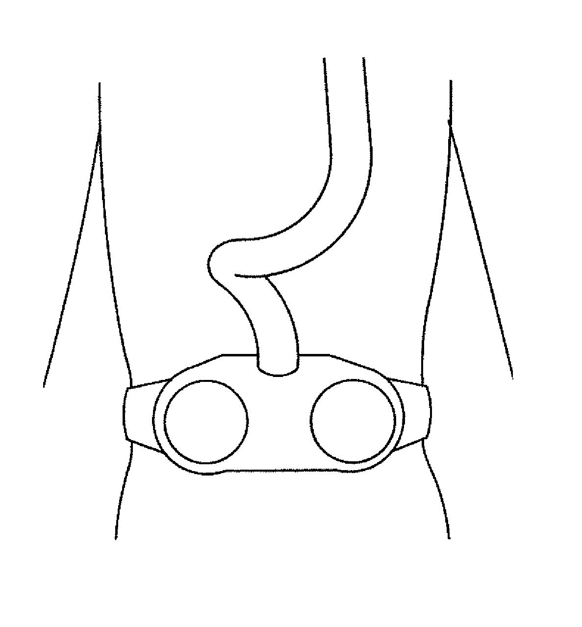
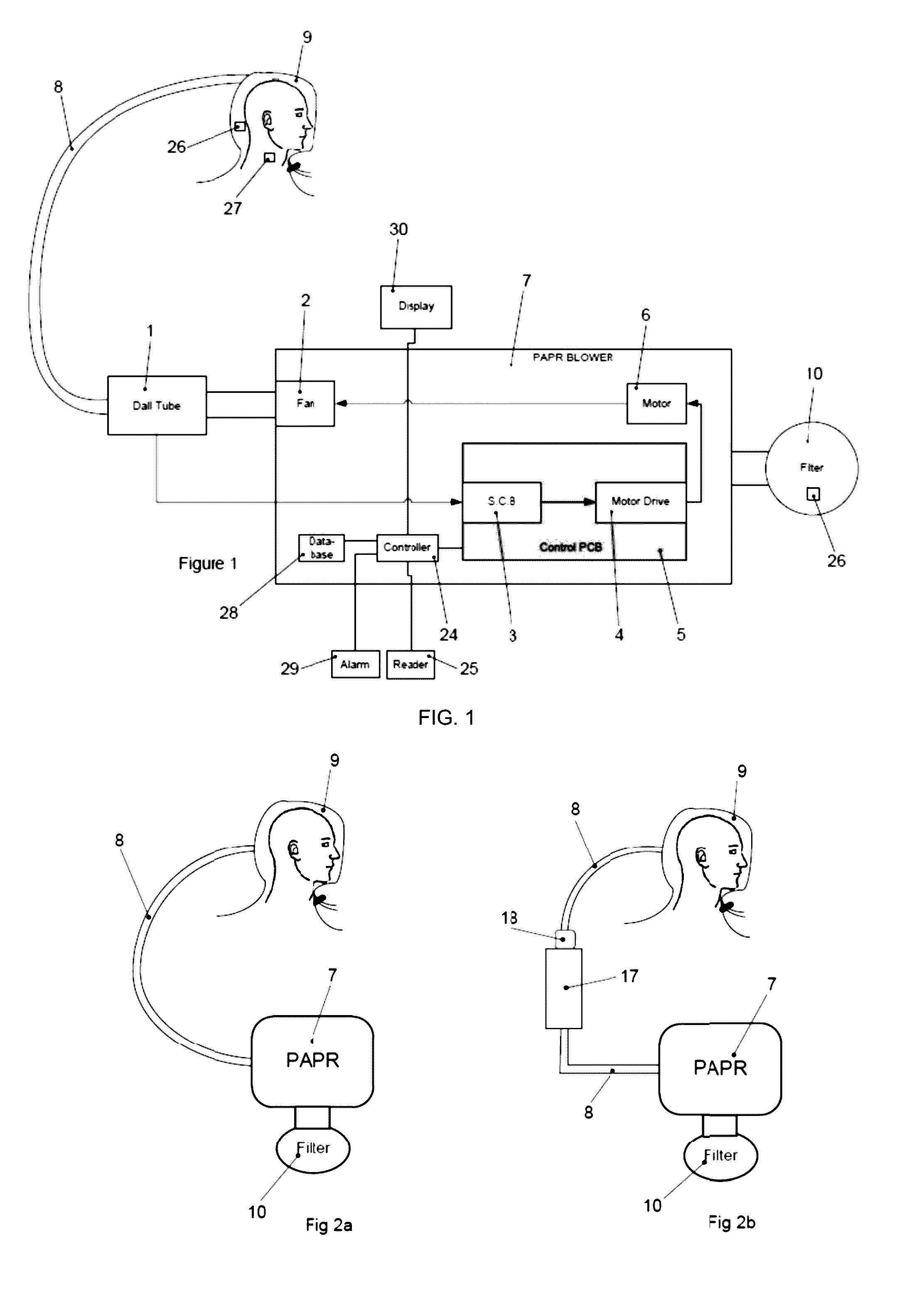
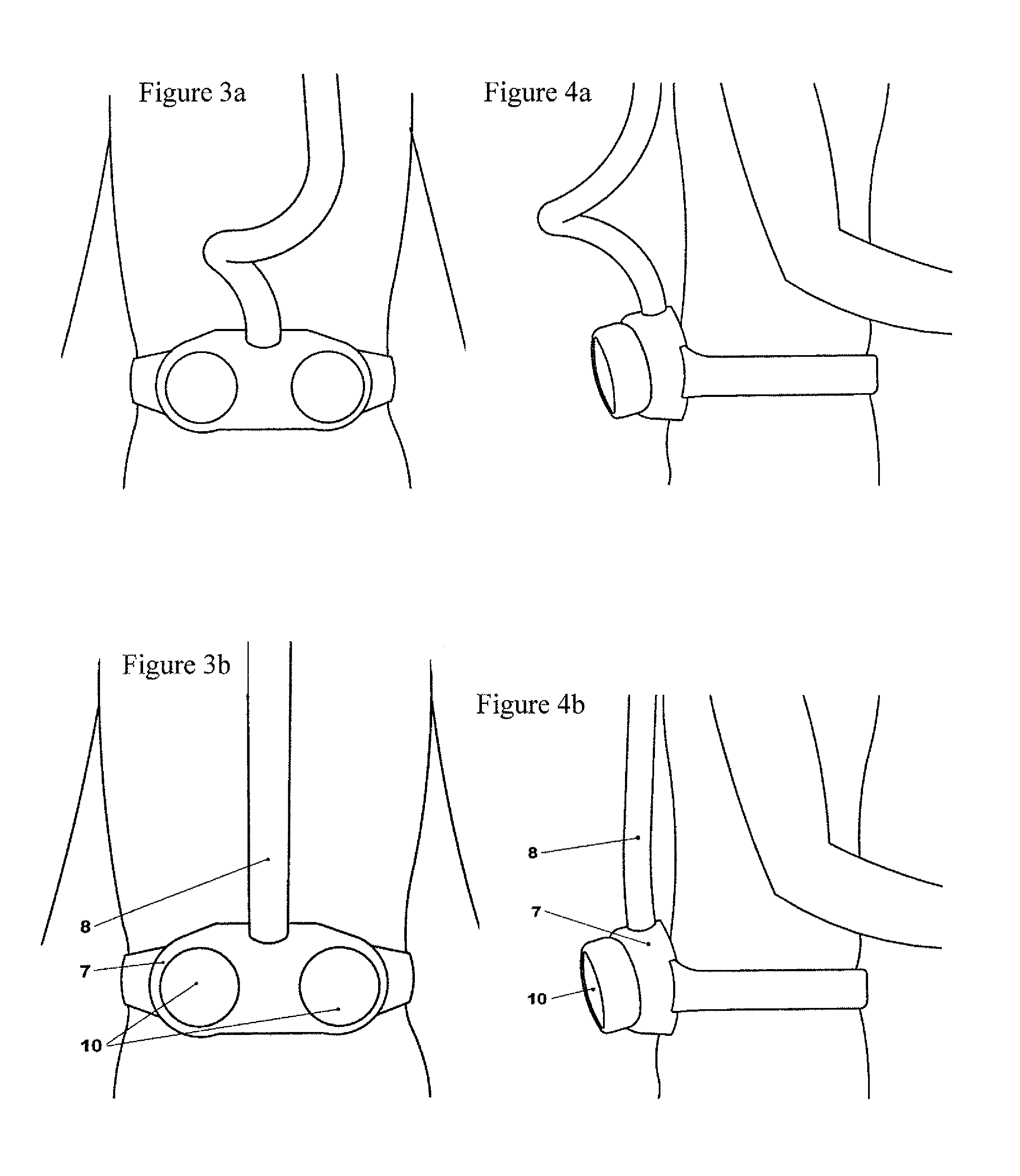
[0067]Referring first to FIG. 1, there is shown a Powered Air Purified Respirator (hereinafter PAPR) 7, of a type generally known in which filter(s) 10 are fixed to the PAPR 7 so as to filter air as it is drawn into the PAPR. The PAPR contains a motor 6 that drives an impellor in a volute 2 so as to suck air into the unit and deliver to a headtop / mask 9 via a delivery tube or hose 8.

[0068]Located in line between the impeller and the headtop is a Dall tube 1 which is utilised to monitor the flow rate of air supplied to the headtop. The air supplied by the fan (impellor and volute 2) pulls contaminated air through the filter(s) 10 and pushes the breathable air through the Dall tube 1. The Dall tube 1 (shown in more detail in FIG. 6) has two pressure sensing points—a high pressure sensing point 1a and a low pressure sensing pint 1b, that connect to a pressure differential sensor which sends a signal to a signal conditioning block 3. The pressure differential sensor may be composed of t...


PUM


Abstract

A safety breathing apparatus has a sensor for measuring the difference in pressure between two point in the gas delivered to a head unit. The sensor is used to measure the difference in the pressure of the gas supplied through the apparatus between the two points in the gas flow, and the pressure difference is then used to calculate the gas flow rate.

Description

CROSS-REFERENCE TO RELATED APPLICATIONS[0001]The present application is a continuation of U.S. patent application Ser. No. 13 / 521,024 (the “'024 Application”), which was filed Jun. 17, 2013 and is incorporated by reference in its entirety. The '024 Application claims priority to International Application No. PCT / GB2010 / 051803 (the “'803 Application”), filed October 27, 2010, which claims priority to Great Britain Patent Application No. GB 1005293.4 (the '293 Application“), filed Mar. 29, 2010, Great Britain Patent Application No. GB 0919277.4 (the '277 Application”), filed Nov. 3, 2009, and Great Britain Patent Application No. GB 0919211.3 (the “'211 Application”), filed November, 2, 2009. The '803 Application, the '293 Application, the '277 Application, and the '211 Application are also incorporated by reference in their entirety.FIELD OF THE INVENTION[0002]The present invention relates to improvement to powered air filtering devices incorporating a helmet, mask or hood with partic...

Claims


Application Information

Patent Timeline
Patent Type & Authority Applications(United States)
IPC IPC(8): A62B9/00A62B18/02A62B18/08A62B9/04A62B18/00A62B7/02A62B7/10
CPCA62B9/006A62B7/02A62B18/02A62B18/088A62B9/04A62B18/006A62B7/10A61M16/024A61M16/0051A62B7/00A62B9/00A62B18/00G01F1/34A61M16/0066A61M16/06A61M16/0875A61M16/105
Inventor ZWOLINSKY, ALBERT F.MARSHALL, RICHARD D.HALL, CHRISTOPHER G.
Owner SCOTT HEALTH & SAFETY
Why Eureka
Try Eureka