Hydraulic system for driving a vibratory mechanism

a technology of hydraulic system and vibratory mechanism, which is applied in the direction of accumulator installation, servomotor, way, etc., can solve the problems of large amount of energy lost in throttling, large amount of required torque output of engine shaft, and large amount of required fluid flow, etc., to achieve high flow volume, reduce excessive and potentially damaging pressure build-up, and reduce the effect of power consumption

Active Publication Date: 2016-11-03
VOLVO CONSTR EQUIP
View PDF6 Cites 6 Cited by
  • Summary
  • Abstract
  • Description
  • Claims
  • Application Information

AI Technical Summary

Benefits of technology

[0008]In conventional hydraulic systems for driving a vibratory system a power source, typically a diesel engine drives a single fixed displacement hydraulic pump for delivering hydraulic fluid to a hydraulic motor via a control valve assembly. Relief pressure valves provide a safe and proper operation of the hydraulic system by eliminating excessive and potentially damaging pressure build-up in the hydraulic system. The single fixed displacement pump has to have sufficient flow capacity to accelerate the hydraulic motor and the associated vibratory mechanism to a nominal speed. During the acceleration period of the vibratory mechanism the single fixed displacement hydraulic pump constantly delivers high flow volumes. Due to the constant flow of the pump approximately half of this energy will be dissipated at the pressure relief valves, because the hydraulic motor at the eccentrics speed up continuously and the flow through the hydraulic pump increases from zero to full pump flow. The pressure relief valve, which influences the acceleration level of the hydraulic motor, is selected to avoid any damages of the hydraulic system due to excessive pressure. The single fixed displacement pump system will consequently require a relatively high power output from the engine during the complete acceleration time.
[0009]The hydraulic system according to a first aspect comprises a first and a second hydraulic pump fluidly connected to the at least one hydraulic motor and both are arranged for supplying pressurised hydraulic fluid to the hydraulic motor. This arrangement enables, by proper dimensioning and operation of the first and second hydraulic pumps, improved fuel efficiency of the eccentric drives while maintaining a quick acceleration phase of the eccentric drive. These advantageous aspects may for example be realised by supplying pressurised hydraulic fluid to the at least one hydraulic motor from only one of the first and second hydraulic pumps during a first part of a hydraulic motor acceleration phase, and to supply pressurised hydraulic fluid to the at least one hydraulic motor from both of the first and second hydraulic pumps during a second part of the hydraulic motor acceleration phase. This arrangement has the advantage that each hydraulic pump may exhibit a smaller displacement compared with the displacement of the single fixed displacement pump according to the conventional solution. Operation of a smaller displacement pump requires less engine power than operation of a larger displacement pump at the same engine speed during the acceleration phase because less flow, i.e. energy will be dissipated at the pressure relief valve. After a certain time period of operation of a single hydraulic pump also the second hydraulic pump is operated. The combined displacement of the first and second hydraulic pumps may be selected to correspond to the displacement of the conventional single pump design, such that the hydraulic motor may be accelerated to the desired speed.
[0010]According to farther aspect of the disclosure, the hydraulic, system further may comprise a hydraulic accumulator fluidly connected to the at least one hydraulic motor. Thereby at least part of the kinetic energy of the eccentric can during deceleration thereof be converted to hydraulic energy and temporarily stored in the hydraulic accumulator, and upon later acceleration of the eccentric the stored hydraulic energy can be used to accelerate the eccentric. Use of the accumulator enables significant reduction or even a complete elimination of dissipation of energy at the relief valve, thereby reducing overall fuel consumption.

Problems solved by technology

In traditional hydraulic systems for vibration drives comprising a fixed displacement pump a relatively large amount of energy is lost in throttling; losses caused by the difference in supplied flow by the pump and consumed flow by the motor.
The recovered amount of rotary energy of the eccentrics is always less than the energy needed to accelerate the eccentrics to the same speed again due to normal unavoidable energy losses associated with the energy conversion and friction in bearings etc.
However, the required additional energy in form of additional fluid flow is relatively small since the energy loss is relatively small.
Furthermore, because the swept volume of the smaller pump is relatively small, even at high pressure the required torque output from the engine shaft is relatively small.

Method used


Image

  • Hydraulic system for driving a vibratory mechanism
  • Hydraulic system for driving a vibratory mechanism
  • Hydraulic system for driving a vibratory mechanism

Examples


first embodiment

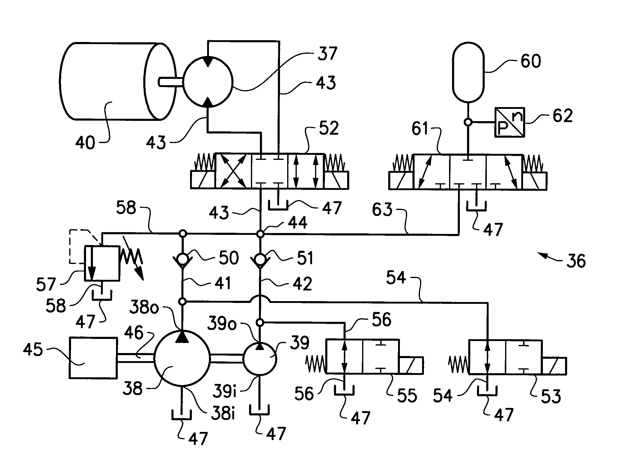
[0039]FIG. 3 shows very schematically the hydraulic system 36 for driving a vibratory mechanism 40 of the compaction roller according to the disclosure. The vibratory mechanism 40 typically comprises at least one eccentric 30 and optionally also driving shaft 28. The hydraulic system 36 comprising a hydraulic motor 37 connected to vibratory mechanism 40. The hydraulic, system 36 further comprises a first and a second hydraulic pump 38, 39 fluidly connected to the at least one hydraulic motor 37 and arranged for supplying pressurised hydraulic fluid to the hydraulic motor 37 via fluid feed paths 4142, 43. The first and second hydraulic pumps 38, 39 are fluidly connected to the hydraulic motor 37 partly via first and second individual feed paths 4142, and partly via a common feed path 43. The first and second individual feed paths 4142 meet and merge to the common feed path 43 at a coupling point 44.

[0040]A single power source 45, such as a combustion engine or electrical motor is rot...

second embodiment

[0049]FIG. 6 shows the hydraulic system 36, which additionally comprises a hydraulic accumulator 60 fluidly connected to the outlet ports 38o, 39o of the first and second pumps 38, 39, as well as the hydraulic motor 37. The accumulator 60 is connected to the common feed path 43. The accumulator 60 is fluidly connected and charged by the hydraulic motor 37 via an accumulator control valve 61 during an eccentric deceleration phase. A pressure switch or pressure sensor 62 may be provided in the feed path 63 for the purpose of detecting the accumulator charge status. In the next acceleration phase the accumulator is fluidly connected to hydraulic motor 37 and discharged during the acceleration phase. Only the energy loss associated with charging and discharging the accumulator must be supplementary supplied from a hydraulic pump for accelerating the eccentric 30 back to nominal speed. Since the energy loss associated with charging and discharging the accumulator normally is relatively s...

third embodiment

[0052]With reference to FIG. 7 which shows the hydraulic system 36, variation in eccentric operating frequency can alternatively be arranged by providing one 39 of the first and second hydraulic, pumps 38, 39 is a variable displacement pump and the other 38 of the first and second hydraulic pumps 38, 39 is a fixed displacement pump. Preferably, the smaller displacement pump 39 is the variable displacement pump because of the lower costs of a small variable displacement pump compared with a large variable displacement pump. The variable displacement pump 39 is preferably a continuously variable displacement pump that is capable of providing any flow level between a min and max flow level. Consequently, the range of possible eccentric, frequency is significantly increased compared with the solution having two fixed displacement pumps as shown in FIG. 6.

[0053]For each of the embodiments 1-3 described above both the first and second feed paths 4142 are free from any additional hydraulic...


PUM


Abstract

A hydraulic system for driving a vibratory mechanism of a compaction roller includes at least one hydraulic motor connectable to a vibratory mechanism and a first hydraulic pump fluidly connected to the at least one hydraulic motor and arranged for supplying pressurised hydraulic fluid to the at least one hydraulic motor. The hydraulic system further includes a second hydraulic pump fluidly connected to the at least one hydraulic motor and arranged for supplying pressurised hydraulic fluid to the at least one hydraulic motor. A corresponding method for controlling a vibratory mechanism of a compaction roller is also provided.

Description

BACKGROUND AND SUMMARY[0001]This disclosure relates to a hydraulic system for driving a vibratory mechanism of a compaction roller. The hydraulic system comprising at least one hydraulic motor connectable to vibratory mechanism and a hydraulic pump fluidly connected to the at least one hydraulic motor and arranged for supplying pressurised hydraulic fluid to the at least one hydraulic motor. The disclosure also relates to a corresponding method for controlling a vibrator mechanism of a compaction roller. The hydraulic system may be installed on a compaction machine comprising a single, dual or more compaction rollers.[0002]Compaction machines are used for compacting the ground on construction work sites to accomplish a smooth and flat ground surface, in particular in earthwork and road construction. The ground surface may comprise soil, gravel, asphalt and the like. The compaction machine comprises at least one substantially cylindrical compaction roller that presses the soil flat. ...

Claims


Application Information

Patent Timeline
Patent Type & Authority Applications(United States)
IPC IPC(8): E01C19/28F15B11/17F15B21/02F15B1/04
CPCE01C19/286F15B1/04F15B11/17F15B21/02F15B2211/75E01C19/282F15B2211/20546F15B2211/20538F15B2211/20576E01C19/28F15B2211/2654F15B1/024
Inventor WIKTOR, ROLANDLILLJEBJON, ERIK GUSTAF
Owner VOLVO CONSTR EQUIP
Why Eureka
Try Eureka