Charging profiles for a storage device in an energy generation system

a technology of energy generation system and charging profile, which is applied in the direction of greenhouse gas reduction, instruments, computer control, etc., can solve the problems of inability to accurately predict storms at downstream eg sites, inability to use the second charging profile, and inability to meet the requirements of the system. to achieve the effect of limiting the time of using the second charging profile and prolonging the life of the storage devi

Inactive Publication Date: 2016-11-03
SOLARCITY
View PDF5 Cites 71 Cited by
  • Summary
  • Abstract
  • Description
  • Claims
  • Application Information

AI Technical Summary

Benefits of technology

[0005]In certain embodiments, a computer-implemented method for an energy site includes detecting an energy storage device operatively coupled to the energy site, determining an energy storage capacity of the energy storage device, detecting an electrical grid operatively coupled to the energy site, receiving event data corresponding to an event affecting the electrical grid, determining a probability that the electrical grid will experience a power outage based on the event data, charging the storage device according to a first charging profile when the probability is below a predetermined threshold value, and charging the storage device according to a second charging profile when the probability is at or above the predetermined threshold value. In some cases, the event data can be associated with at least one of local weather data, geological data, social media data, or local alert data. The event data can correspond to the event occurring over a predetermined period of time. The storage device can be charged according to the first charging profile under normal operating conditions. In some cases, the method can further include receiving a user input corresponding to a manual selection of the second charging profile, and charging the storage device according to the second charging profile. Further implementations can include receiving a control signal from a control server, the control signal corresponding to an automated selection of the second charging profile, and charging the storage device according to the second charging profile.
[0006]In some embodiments, a computer-implemented system includes one or more processors, and one or more non-transitory computer-readable storage mediums containing instructions configured to cause the one or more processors to perform operations including determining an energy storage capacity of an energy storage device operatively coupled to a grid-connected energy generation site, receiving weather data corresponding to a weather forecast over a predetermined period of time, calculating a probability that the electrical grid will experience a power outage based on the weather data, charging the storage device according to a first charging profile in response to the probability being below a predetermined threshold value, and charging the storage device according to a second charging profile in response to the probability being at or above the predetermined threshold value.
[0007]In certain embodiments, a maximum charge set point of the storage device for the first charging profile is less than the maximum storage capacity of the storage device, and the maximum charge set point of the storage device for the second charging profile is greater than the maximum charge set point of the first charging profile. The method can further include limiting a time of using the second charging profile to e

Problems solved by technology

Despite these improvements, the power output for PV-based EG systems remain susceptible to bad weather conditions, including storm systems and dense cloud cover.
Bad weather conditions can greatly reduce an amount of sunlight that reaches PV-based EG system

Method used


Image

  • Charging profiles for a storage device in an energy generation system
  • Charging profiles for a storage device in an energy generation system
  • Charging profiles for a storage device in an energy generation system

Examples


an embodiment

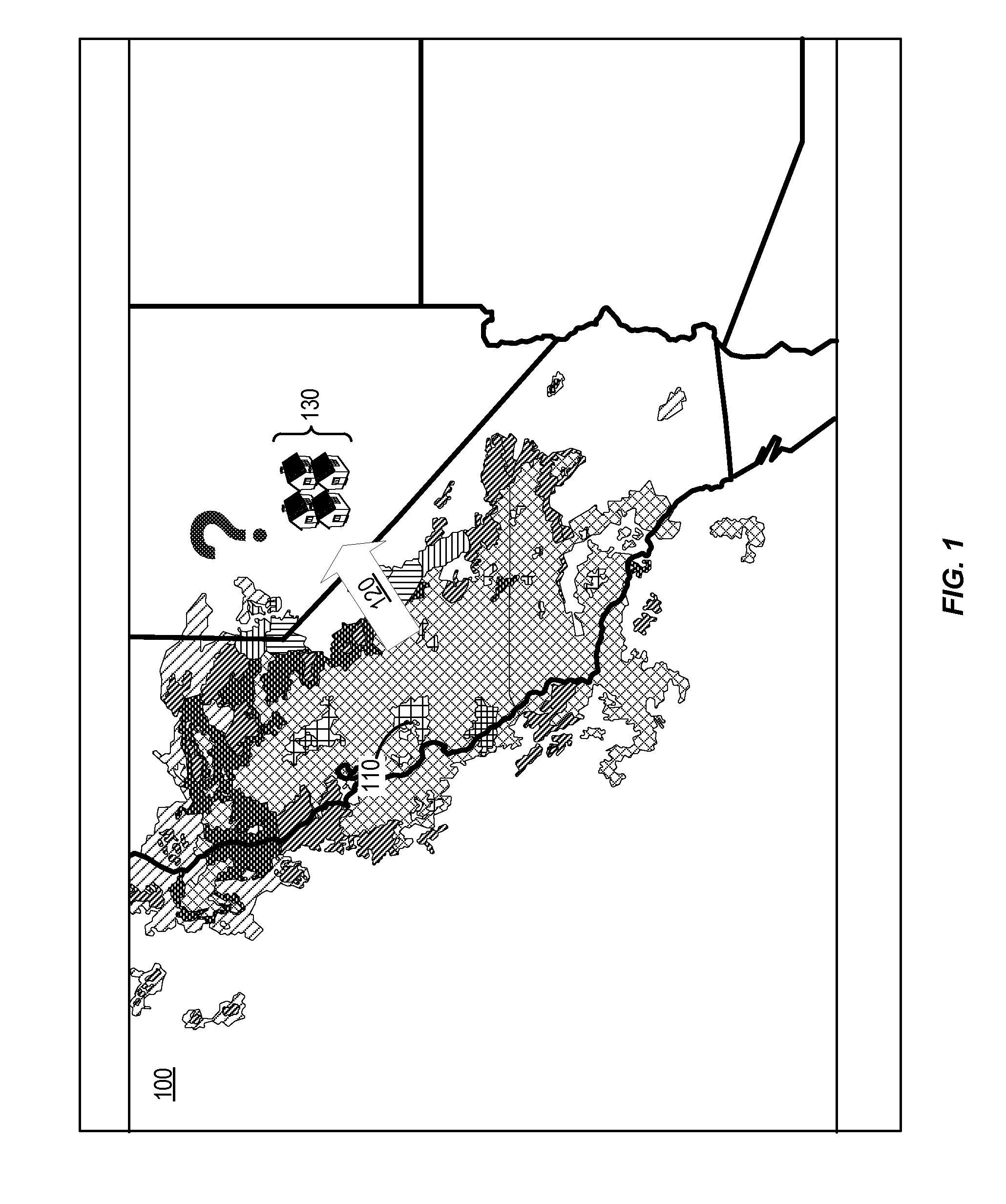
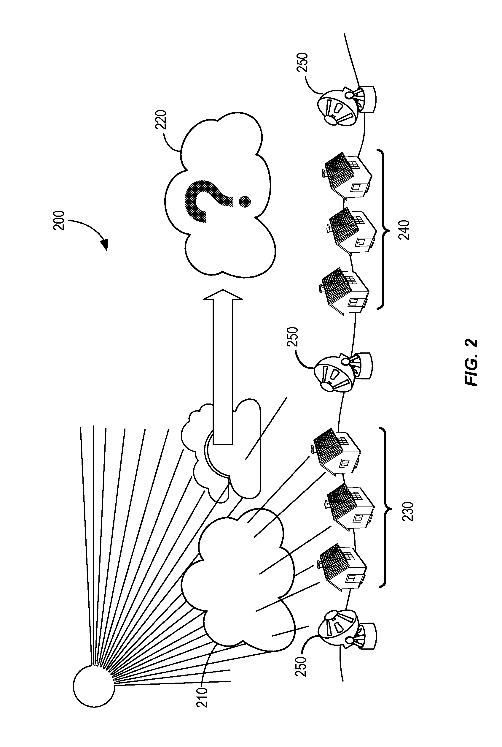
[0046]FIG. 4 shows aspects of a weather tracking system 400 using aspects of one or more PV-based EG sites, according to certain embodiments. Weather tracking system 400 can be used to track and characterize a weather pattern 410 over a number of PV-based EG sites 430 and forecast its effects on downstream EG sites 440. A number of PV-based EG sites are shown in locations across the State of California, U.S.A. Each EG site depicted can represent 1 EG site, 10 EG sites, 1000 EG sites, or any suitable representation. Weather patterns 410, 420 can include one or more clouds (i.e., cloud cover) that can block an amount of sunlight from reaching certain EG sites.

[0047]Weather tracking system (“system”) 400 has significant advantages over all conventional systems, including aspects of those shown in FIG. 1-3. System 400 utilizes the hardware and infrastructure in existing EG sites to perform the weather tracking operations. Thus, system 400 has virtually unlimited scalability with little ...


PUM


Abstract

A computer-implemented method for an energy generation site includes detecting an energy storage device and its storage capacity, detecting an electrical grid operatively coupled to the energy generation site, and receiving event data corresponding to an event affecting the electrical grid. The method further includes determining a probability that the electrical grid will experience a power outage based on the event data, and charging the storage device according to a first charging profile or a second charging profile based on the probability. A maximum charge set point of the storage device for the first charging profile is less than the maximum storage capacity of the storage device, and the maximum charge set point for the second charging profile is at the maximum storage capacity of the storage device. The event data can be weather data, geological data, social media, or local alert data.

Description

CROSS REFERENCE TO RELATED APPLICATIONS[0001]This claims the benefit of U.S. Provisional Application No. 62 / 155,444, filed Apr. 30, 2015, which is hereby incorporated by reference for all purposes.BACKGROUND[0002]In recent years, climate change concerns, federal / state initiatives, and other factors have driven a rapid rise in the installation of renewable energy generation (EG) systems (i.e., systems that generate energy using renewable resources such as solar, wind, hydropower, etc.) at residential and non-residential sites. Solar photovoltaic (PV) systems, in particular, have been very popular EG systems.[0003]PV-based EG systems have continued to improve as new innovations lead to lower manufacturing and installation costs, higher solar panel efficiencies, and greater control over energy distribution. Despite these improvements, the power output for PV-based EG systems remain susceptible to bad weather conditions, including storm systems and dense cloud cover. Bad weather conditi...

Claims


Application Information

Patent Timeline
IPC IPC(8): H02J7/00H02M7/44H02J7/35
CPCH02J7/007H02M7/44H02J7/0052H02J7/35Y04S10/123Y04S10/14H02J3/32G05F1/67H02J2203/20H02J2300/22H02J2300/24H02J3/381Y02E10/56Y02E40/70Y02E60/00Y04S40/20H02J13/00002Y04S10/30G05B15/02Y02E70/30H02J7/00
Inventor CARLSON, ERIC DANIELHOBBS, TARA ELIZABETHRIVE, PETER
Owner SOLARCITY
Why Eureka
Try Eureka