Electromagnetic actuator and solenoid-valve device

a solenoid valve and actuator technology, applied in the direction of valve operating means/releasing devices, magnets, magnetic bodies, etc., can solve the problems of increasing electric power consumption, deteriorating fuel efficiency of vehicles, affecting the efficiency of magnetic circuits, etc., and achieves simple configuration and reduced size, weight and cost.

Inactive Publication Date: 2016-11-10
HONDA MOTOR CO LTD
View PDF5 Cites 10 Cited by
  • Summary
  • Abstract
  • Description
  • Claims
  • Application Information

AI Technical Summary

Benefits of technology

[0018]The electromagnetic actuator in accordance with the present invention and the solenoid-valve

Problems solved by technology

This causes a problem that an increase in electric power consumption required for speed control contributes to deterioration of fuel efficiency of a vehicle.
Thus, the needle without any iron core could deteriorate magnetic reluctance around the coil degenerates in a magnetic field g

Method used


Image

  • Electromagnetic actuator and solenoid-valve device
  • Electromagnetic actuator and solenoid-valve device
  • Electromagnetic actuator and solenoid-valve device

Examples


Embodiment Construction

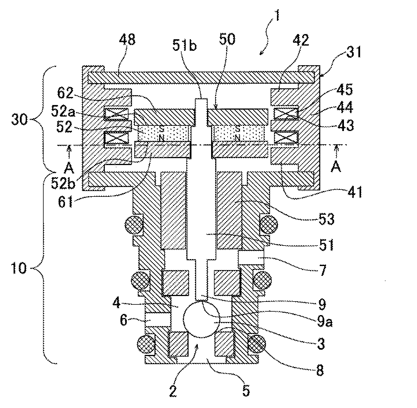
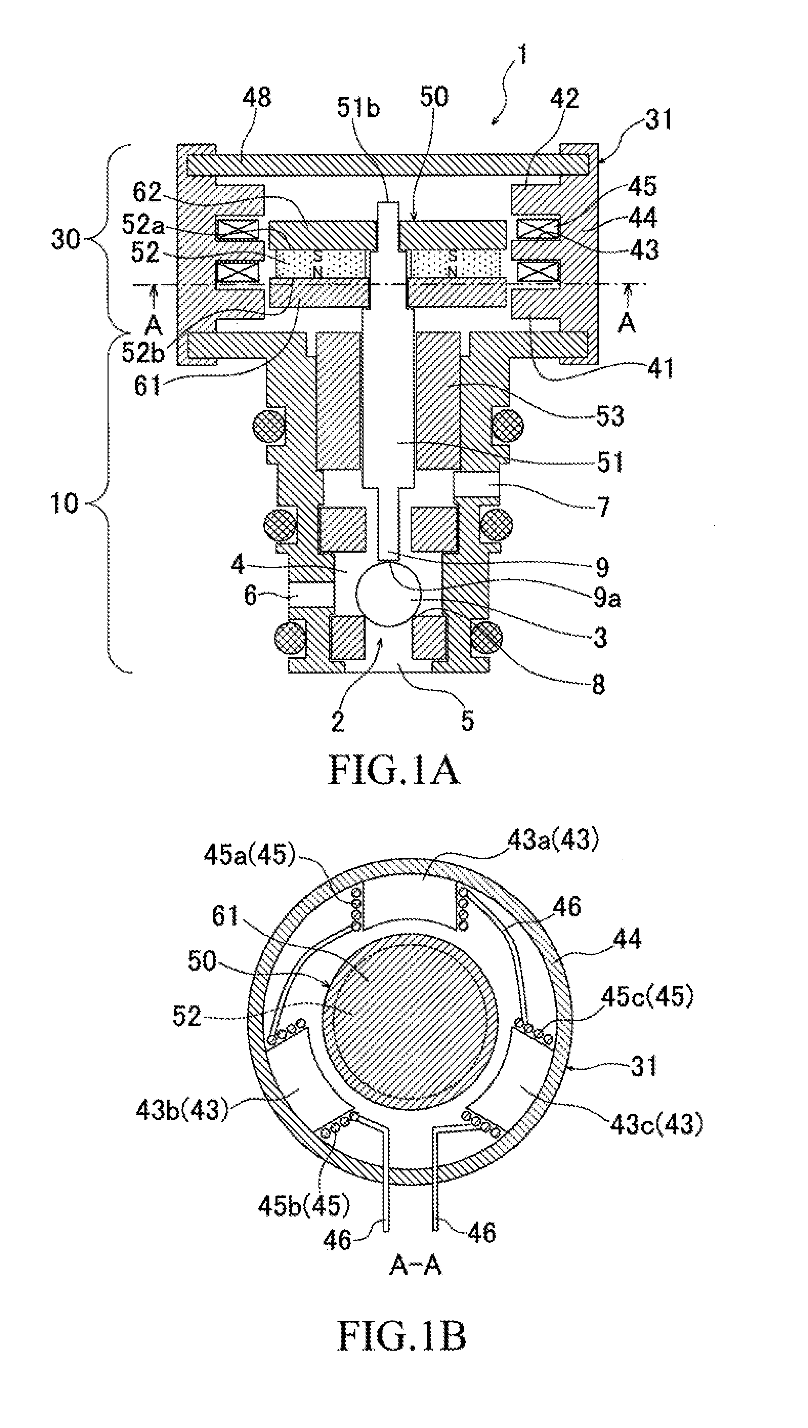
[0023]Hereinafter, an embodiment of the present invention will be described in detail with reference to the appending drawings. FIG. 1A and FIG. 1B are views illustrating an exemplary configuration of a solenoid-valve device oil according to one embodiment of the present invention, of which FIG. 1A is a sectional side view of the solenoid-valve device, and FIG. 1B is a schematic sectional view of a part corresponding to an A-A arrow view of FIG. 1A. The solenoid-valve device 1 shown in the same figure is mounted in a hydraulic control unit of an automotive automatic transmission, and a device for stitching opening and closing of the oil passage, with which the hydraulic control device is provided, where control hydraulic fluid circulates. This solenoid-valve device 1 includes a valve part 10 provided with a ball valve (valve body) 3 for switching opening and closing of the oil passage 2, and an electromagnetic actuator section (electromagnetic actuator) 30 for driving the ball valve...


PUM


Abstract

An electromagnetic actuator is provided that can achieve reduction in size, weight and cost by a simple configuration, and a solenoid-valve device provided therewith. The electromagnetic actuator section includes fixed pole pieces that a middle of three fixed magnetic poles has, and coils wound around the fixed pole pieces. The coils are wound in the same winding direction. The needle has first and second stabilization points corresponding to the fixed magnetic poles on both sides in the axial direction, and a third stabilization point corresponding to the middle fixed magnetic pole, as stabilization points at which a stationary state can be maintained when the coil is unenergized.

Description

TECHNICAL FIELD[0001]The present invention relates to an electromagnetic actuator including a cylindrical stator and a needle that reciprocates inside the stator in the axial direction and a solenoid-valve device including the electromagnetic actuator.BACKGROUND ART[0002]Conventionally, a hydraulic control unit structured to switch hydraulic pressure in an oil passage for hydraulic control using a solenoid valve is employed as a means for changing gear stages of an automatic transmission. The solenoid valve in this case has a valve structure of the normally open type or the normally closed type, configured to apply electricity (electric current or voltage) to the solenoid valve to perform an operation necessary for switching the oil passage.[0003]In the prior arts, it is necessary to continuously apply electricity to the solenoid valve to produce hydraulic pressure necessary for the oil passage for hydraulic control. Further, as a transmission is more staged in recent years, one uni...

Claims


Application Information

Patent Timeline
IPC IPC(8): F16K31/08H01F7/16F16K31/06
CPCF16K31/082H01F7/1615F16K31/0631F16K31/0679
Inventor NEMOTO, HIROTOMI
Owner HONDA MOTOR CO LTD
Why Eureka
Try Eureka