Passive wireless sensor

a wireless sensor and wireless technology, applied in the field of passive wireless sensors, can solve the problems of limited read-out distance, limited lifetime, and limited lifetime of wireless sensors

Active Publication Date: 2016-11-10
METSO OUTOTEC (FINLAND) OY
View PDF11 Cites 32 Cited by
  • Summary
  • Abstract
  • Description
  • Claims
  • Application Information

AI Technical Summary

Benefits of technology

[0023]In an embodiment, the passive wireless transponder comprises one or more of a high pass filter between the antenna and the rectifier, a low pass filter

Problems solved by technology

However, wireless sensors also have some drawbacks such as limited lifetime due to battery, limited read-out distance due to attenuation and interference, security issues because of the uncontrollable propagation of the signal and potentially low speed of communication.
However, the battery on board limits the life time and also increases the size and weight.
Due to more complex circuit, the price of an active sensor can be much higher than that of a passive sensor.
The need to use a piezoelectric material for the sensing element limits possible applications.
In addition, SAW tags only enable hard-coded identification (ID), and they do not provide any memory to the chip.
These sensors require nearfield coupling to the reade

Method used


Image

  • Passive wireless sensor
  • Passive wireless sensor
  • Passive wireless sensor

Examples


Embodiment Construction

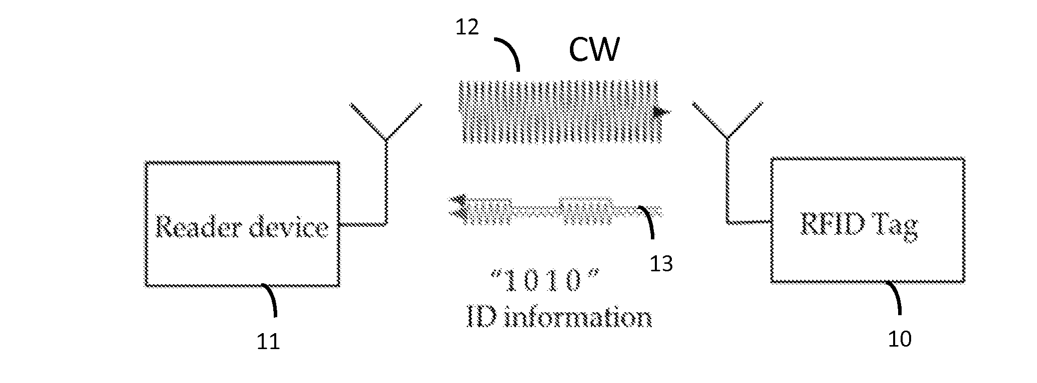
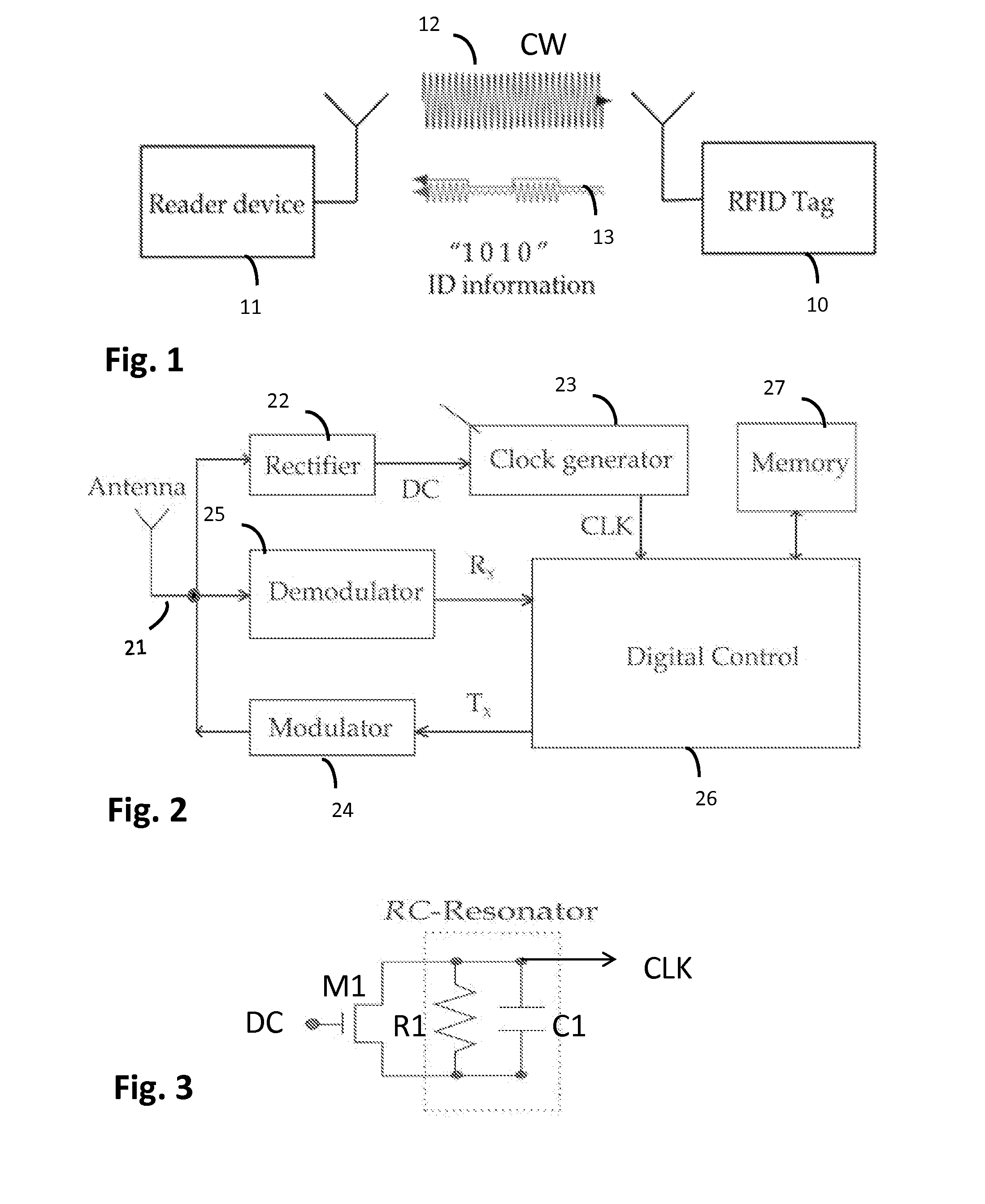
[0043]FIG. 2 shows a functional block diagram illustrating an example of radio frequency identity (RFID) transponder (tag) architecture. In the illustrated example the RFID tag 10 may comprise an antenna 21 directly matched to the tag's front end impedance (matching circuit is not shown) to communicate with a RFID reader 11; an analogue RF front end that may typically contain rectifier circuitry 22 to convert RF power into a direct current (DC), a clock generator or oscillator 23, a modulator 24 and a demodulator 25. There may also be a logic part or a digital control module 26 that may be configured to provide desired functions, such as to handle interrogating commands, execute the anti-collision protocol, perform the data integrity check, run memory read-write operations, and perform output control and data flow. The logic implementation usually follows a defined standard and a certain associated protocol. Further, memory storage 27 may be provided. Depending on a user's requireme...


PUM


Abstract

The RFID sensor tag may include normal RFID circuits and functions (such as rectifier, modulator, logic and memory) as well as a resonator-based clock generator or oscillator. The oscillator is a stable resonator-based oscillator having a high Q value. The resonator-based oscillator is loaded with a sensor element which tunes the oscillation frequency, i.e. the oscillation frequency is sensitive to the measured quantity. Thereby, a passive RFID sensor with a resonator-based oscillator and a sensor element is provided, wherein the oscillation frequency can be made dependent on the sensor element if sensing is required. The concept is compatible for existing RFID tags and can enable the possibility to measure external quantities with-out reducing the read-out distance.

Description

FIELD OF THE INVENTION[0001]The present invention relates to passive wireless sensors.BACKGROUND OF THE INVENTION[0002]Sensor is a device that transforms a measured quantity into a readable format, typically into an electrical signal. Nowadays, there are commercially available sensors virtually for any measurement purpose. According to the connectivity, sensors can be divided into wireless and wired sensors. Wired sensors are connected via wiring harnesses or cable assemblies to a reader device. Wireless sensors can be read without a physical connection to the sensor, and are often realized equipping the sensor with a radio transceiver. The transmitted radio signal is interpreted by a receiver which converts the wireless signal into a desired output. Wireless operation can be beneficial in many applications, where wired connection is difficult for example due to harsh operating conditions (like temperature and pressure, rotating parts, or cost and complexity of wiring. However, wire...

Claims


Application Information

Patent Timeline
IPC IPC(8): G06K19/07G06K19/077
CPCG06K19/07796G06K19/0723G06K19/0717H04Q2209/47H04Q9/00H04B5/0068
Inventor VIIKARI, VILLE
Owner METSO OUTOTEC (FINLAND) OY
Why Eureka
Try Eureka