Secondary battery and electronic device
a secondary battery and battery technology, applied in the field of secondary batteries and electronic devices, can solve problems such as fatigue destruction, and achieve the effects of high capacity, novel structure, and high reliability of secondary batteries
- Summary
- Abstract
- Description
- Claims
- Application Information
AI Technical Summary
Benefits of technology
Problems solved by technology
Method used
Image
Examples
embodiment 1
[0059]In this embodiment, a secondary battery 110 of one embodiment of the present invention and a manufacturing method thereof are described.
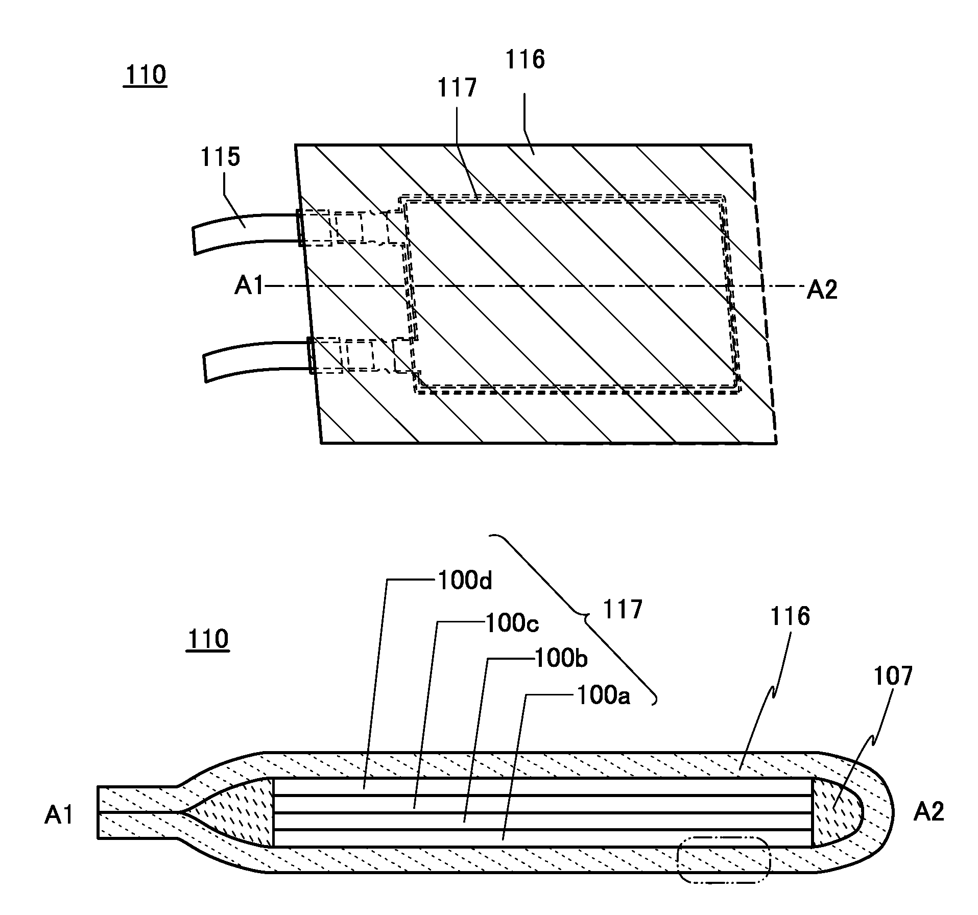
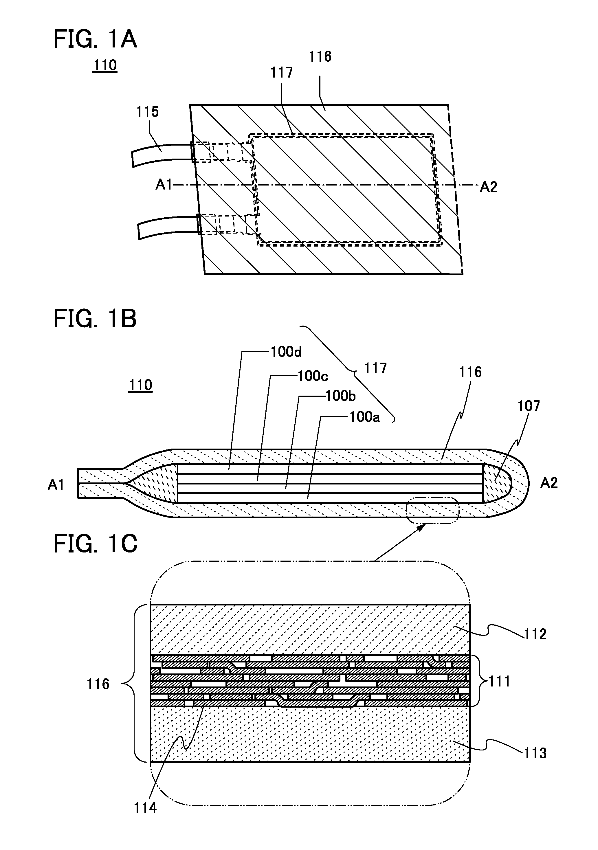
[0060]FIGS. 1A to 1C illustrate the secondary battery 110. The secondary battery 110 in FIG. 1A includes an inner structure 117 surrounded by an exterior body 116. The inner structure 117 includes an electrode and a separator, and the electrode is electrically connected to a lead electrode 115.
[0061]FIG. 1B is a cross-sectional view taken along line A1-A2 in FIG. 1A. FIG. 1C is an enlarged view of the exterior body 116.
[0062]As shown in FIG. 1B, the secondary battery 110 has a structure in which the inner structure 117 and an electrolytic solution 107 are surrounded by the exterior body 116. The inner structure 117 includes a first stack 100a, a second stack 100b, a third stack 100c, and a fourth stack 100d. The number of stacks included in the secondary battery 110 of this embodiment is mainly four; however, it is not limited to this.
[0063]As...
embodiment 2
[0172]In this embodiment, structures of a storage battery of one embodiment of the present invention are described with reference to FIGS. 9A and 9B, FIG. 10, FIG. 11, FIGS. 12A to 12C, and FIGS. 13A to 13E.
[0173]Next, an example of a laminated storage battery will be described with reference to FIG. 9A. When a flexible laminated storage battery is used in an electronic device at least part of which is flexible, the storage battery can be bent as the electronic device is bent.
[0174]A laminated storage battery 500 illustrated in FIG. 9A includes a positive electrode 503 including a positive electrode current collector 501 and a positive electrode active material layer 502, a negative electrode 506 including a negative electrode current collector 504 and a negative electrode active material layer 505, a separator 507, an electrolytic solution 508, and an exterior body 509. The separator 507 is provided between the positive electrode 503 and the negative electrode 506 in the exterior b...
embodiment 3
[0221]A battery management unit (BMU) that can be used in combination with secondary batteries each including the materials described in the above embodiment and transistors that are suitable for a circuit included in the battery management unit will be described with reference to FIG. 18, FIGS. 19A to 19C, FIG. 20, FIG. 21, FIGS. 22A to 22C, FIG. 23, and FIG. 24. In this embodiment, in particular, a battery management unit of a power storage device including battery cells connected in series will be described.
[0222]When a plurality of battery cells connected in series are charged and discharged repeatedly, each battery cell has different capacity (output voltage) from one another due to the variations in characteristics among the battery cells. A discharge capacity of all of the plurality of battery cells connected in series depends on a battery cell with small capacity. The variations in capacity among the battery cells reduces the capacity of the all the battery cells at the time...
PUM
 Abstract
Description
Claims
Application Information
 - R&D
- Intellectual Property
- Life Sciences
- Materials
- Tech Scout
- Unparalleled Data Quality
- Higher Quality Content
- 60% Fewer Hallucinations
Browse by: Latest US Patents, China's latest patents, Technical Efficacy Thesaurus, Application Domain, Technology Topic, Popular Technical Reports.
© 2025 PatSnap. All rights reserved.Legal|Privacy policy|Modern Slavery Act Transparency Statement|Sitemap|About US| Contact US: help@patsnap.com


