Cooling device and data center provided with same

a cooling device and data center technology, applied in the direction of semiconductor/solid-state device details, lighting and heating apparatus, laminated elements, etc., can solve the problems of low cooling capacity of the cooler b>105/b>, low contact probability between vaporized heat medium b>112/b> and heat exchange pipe b>111/b>, etc., to achieve high sealing degree of the inside, reduce pressure loss, and reduce the effect of negative pressure insid

Inactive Publication Date: 2016-11-10
PANASONIC INTELLECTUAL PROPERTY MANAGEMENT CO LTD
View PDF0 Cites 14 Cited by
  • Summary
  • Abstract
  • Description
  • Claims
  • Application Information

AI Technical Summary

Benefits of technology

[0013]An object of the present invention is to lower a temperature of condensed heat medium (hereinafter, working fluid), and enhance cooling capacity.
[0015]Consequently, it is possible to lower a temperature of condensed working fluid to enhance cooling capacity.
[0018]Therefore, in the liquefying chamber and the cooling water chamber of the heat radiation part, heat transfer from the working fluid and the cooling water to the first and second heat radiation fins is effectively performed.
[0023]Additionally, gaps are provided between distal ends of the first heat radiation fins and an inner wall of the heat radiation part, the inner wall facing the partition plate. Consequently, working fluid that flows into the liquefying chamber from the first connection part side to be vaporized can flow through both the gaps, and the openings or the cutouts of the first heat radiation fins, and a pressure loss can be reduced.
[0024]Additionally, an outer periphery of the partition plate can be also welded to an inner surface of the heat radiation part. Consequently, it is possible to maintain a high sealing degree of the inside of the liquefying chamber, and it is also possible to maintain negative pressure of the inside of the circulation passage that houses the working fluid. Therefore, refrigerant can be continuously circulated with a heat quantity of a semiconductor switching element.

Problems solved by technology

However, there is a problem that contact probability between vaporized heat medium 112 and heat exchange pipe 111 is low, and cooling capacity in cooler 105 is low.

Method used


Image

  • Cooling device and data center provided with same
  • Cooling device and data center provided with same
  • Cooling device and data center provided with same

Examples


first exemplary embodiment

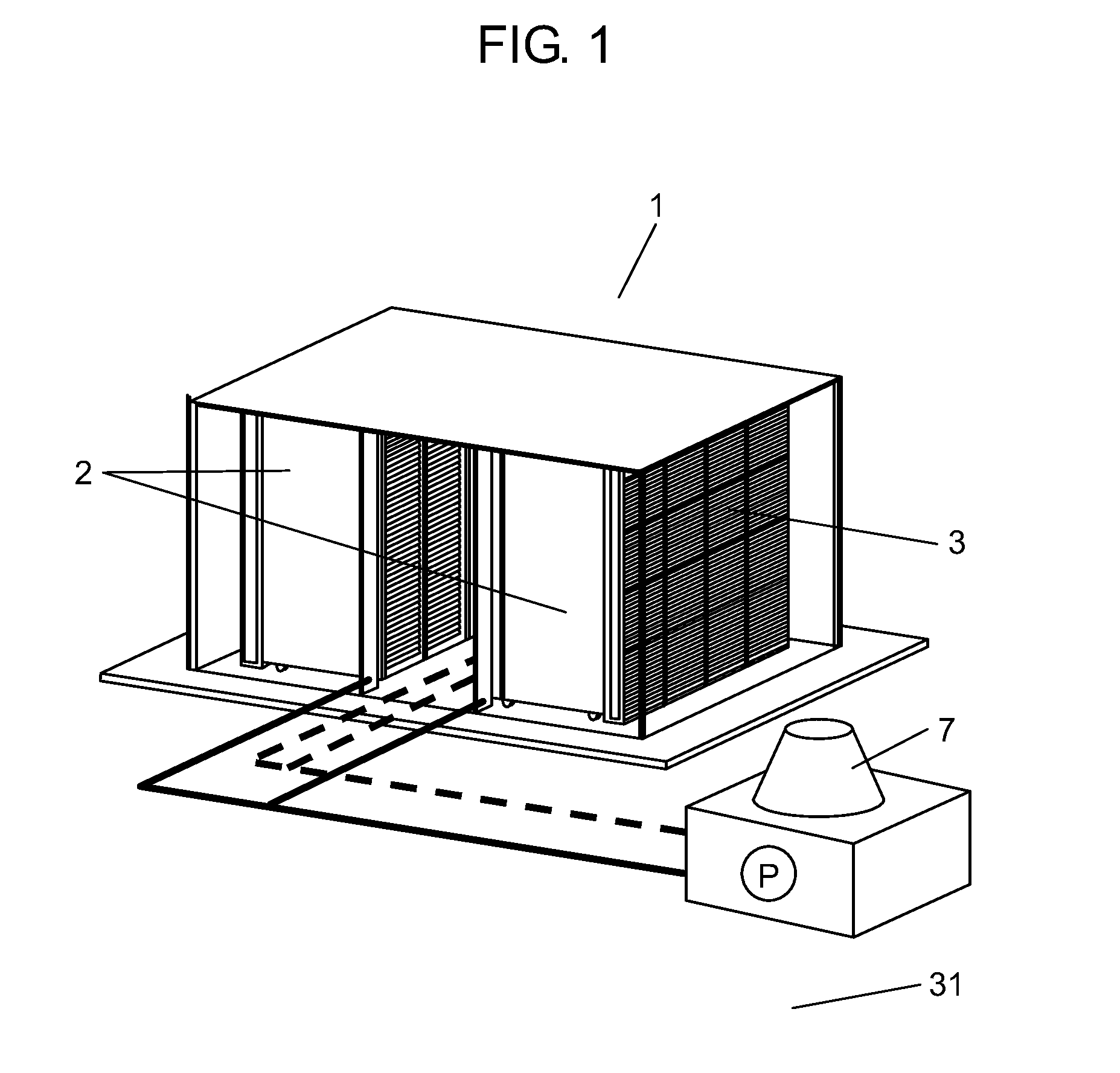
[0059]FIG. 1 is a schematic diagram of data center 1 of a first and embodiment of the present invention. Data center 1 in FIG. 1 houses a plurality of rack type servers 2, as a rack type unit.

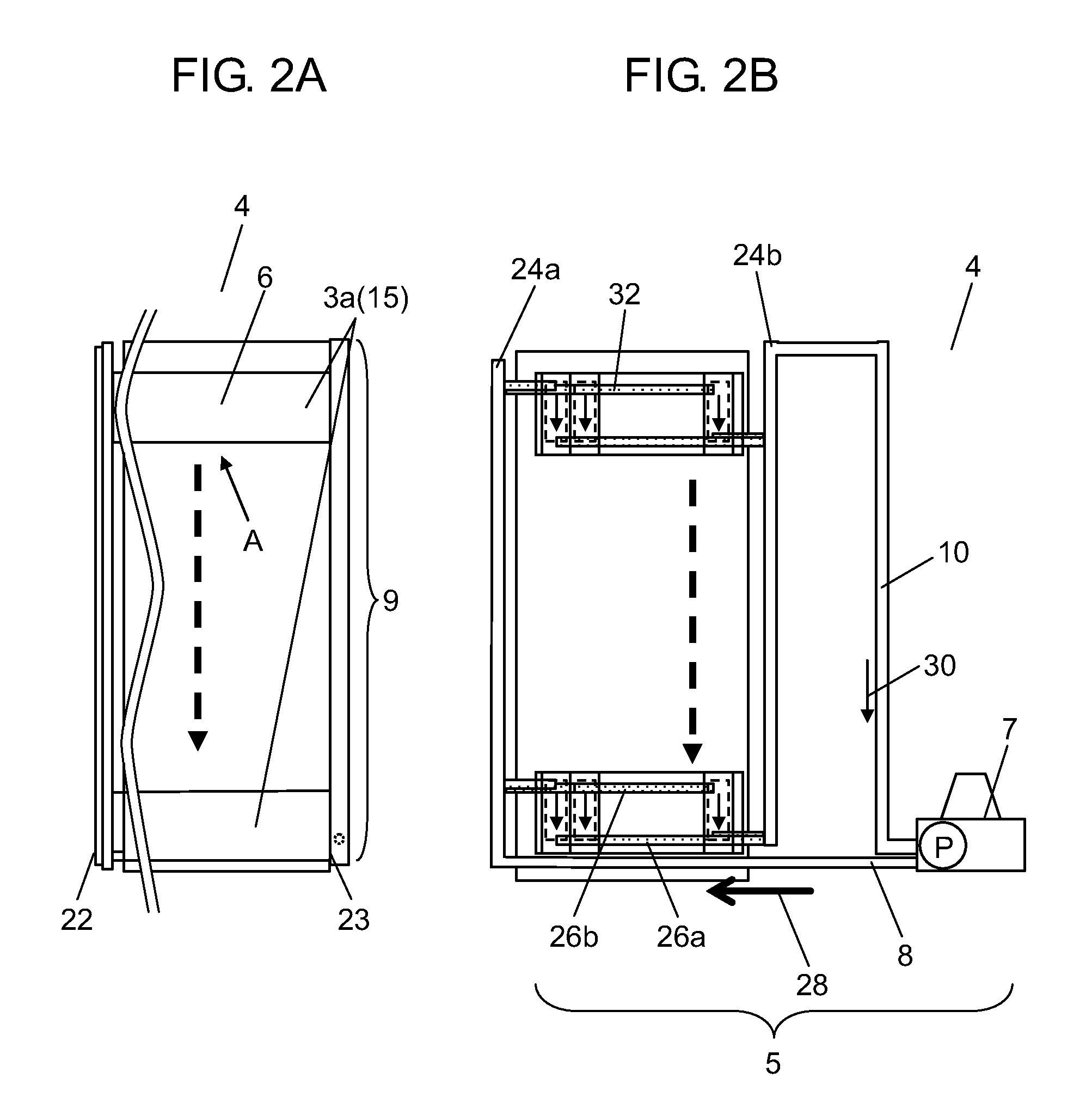
[0060]Rack type servers 2 each have housing 22 (refer to FIG. 2A) provided with openings on a front side and a rear side. FIG. 2A is a side view of cooling device 4 of the first exemplary embodiment of the present invention. Rack type servers 2 each include a plurality of electronic devices 3 in racks of vertical respective stages inside housing 22. In a plurality of electronic devices 3, operation panels or displays are directed to the front side. A plurality of electronic devices 3 are provided with power supply lines and wires for connecting electronic devices 3 or connecting electronic device 3 and an external device on the rear side.

[0061]All the electronic devices do not always include the operation panels or displays. A plurality of rack type servers 2 are installed in data center 1, and...

second exemplary embodiment

[0112]A summary of data center 1 is the same as a summary illustrated in FIG. 1 of the first exemplary embodiment. A plurality of rack type servers 2 are installed in data center 1.

[0113]Rack type servers 2 each have housing 72 (refer to FIG. 8A) provided with openings on a front side and a rear side. FIG. 8A is a side view of cooling device 54 of a second exemplary embodiment of the present invention. Rack type servers 2 each include a plurality of electronic devices 3 in a rack manner inside housing 72. In a plurality of electronic devices 3, operation panels or displays are directed to the front side. A plurality of electronic devices 3 are provided with power supply lines and wires for connecting electronic devices 3 or connecting electronic device 3 and an external device on the rear side.

[0114]All the electronic devices do not always include the operation panels or displays. A plurality of rack type servers 2 are installed in data center 1, and referred to as an electronic com...


PUM


Abstract

A cooling device has a circulation passage that annularly connects heat receiving part, heat radiation passage, heat radiation part, and feedback passage in order, and working fluid housed in the circulation passage, and check valve provided on an upstream side of heat receiving part. Heat radiation part has a liquefying chamber and a cooling water chamber separated by a partition plate. The liquefying chamber has a first connection part connected to heat radiation passage at an upper part of liquefying chamber, and a second connection part connected to feedback passage at a lower part of liquefying chamber, and has a plurality of first heat radiation fins fixed to the partition plate, and having a plurality of openings or cutouts. The cooling water chamber has a cooling water inlet, a cooling water outlet, and a plurality of second heat radiation fins that separate a passage from the cooling water inlet to the cooling water outlet into a plurality of parallel passages.

Description

TECHNICAL FIELD[0001]The present invention relates to a cooling device and a data center provided with the same.BACKGROUND ART[0002]In electronic devices having large power consumption or power conversion circuits of electric vehicles, a large current of several dozen amperes flows through electronic components such as CPUs and semiconductor switching elements, and therefore large heat is generated in these electronic components.[0003]Conventionally, an electronic component is cooled by a cooling device using a loop type heat pipe (refer to PTL 1, for example).[0004]Hereinafter, the conventional cooling device is described with reference to FIG. 14.[0005]As illustrated in FIG. 14, the loop type heat pipe includes loop circuit 103, heat medium 112, cooler 105, heating part 113, and check valve 114. Loop circuit 103 separately includes riser tube 101 and downcomer 102. Heat medium 112 is working fluid sealed in loop circuit 103 under vacuum. Cooler 105 configures a part of loop circui...

Claims


Application Information

Patent Timeline
Patent Type & Authority Applications(United States)
IPC IPC(8): H05K7/20F28D15/02
CPCH05K7/20818H05K7/20409F28D15/0275F28F1/40F28D15/0266F28D15/06H01L23/427F28D2015/0291H01L2924/0002H05K7/20936F28F3/02H01L2924/00
Inventor SATO, KAORUSUZUKI, AYAKA
Owner PANASONIC INTELLECTUAL PROPERTY MANAGEMENT CO LTD
Why Eureka
Try Eureka