Sealing structure and rotary machine

Active Publication Date: 2016-11-17
MITSUBISHI POWER LTD
View PDF7 Cites 10 Cited by
  • Summary
  • Abstract
  • Description
  • Claims
  • Application Information

AI Technical Summary

Benefits of technology

[0018]The present invention, which is provided with a sealing structure that seals a clearance between an outer peripheral surface of a rotor and an inner peripheral surface of a s

Problems solved by technology

However, the leakage steam which passes through the clearance between the tip portion of the

Method used


Image

  • Sealing structure and rotary machine
  • Sealing structure and rotary machine
  • Sealing structure and rotary machine

Examples


Embodiment Construction

[0026]Hereinafter, a steam turbine which is a rotary machine of an embodiment of the present invention will be explained in detail with reference to the drawings.

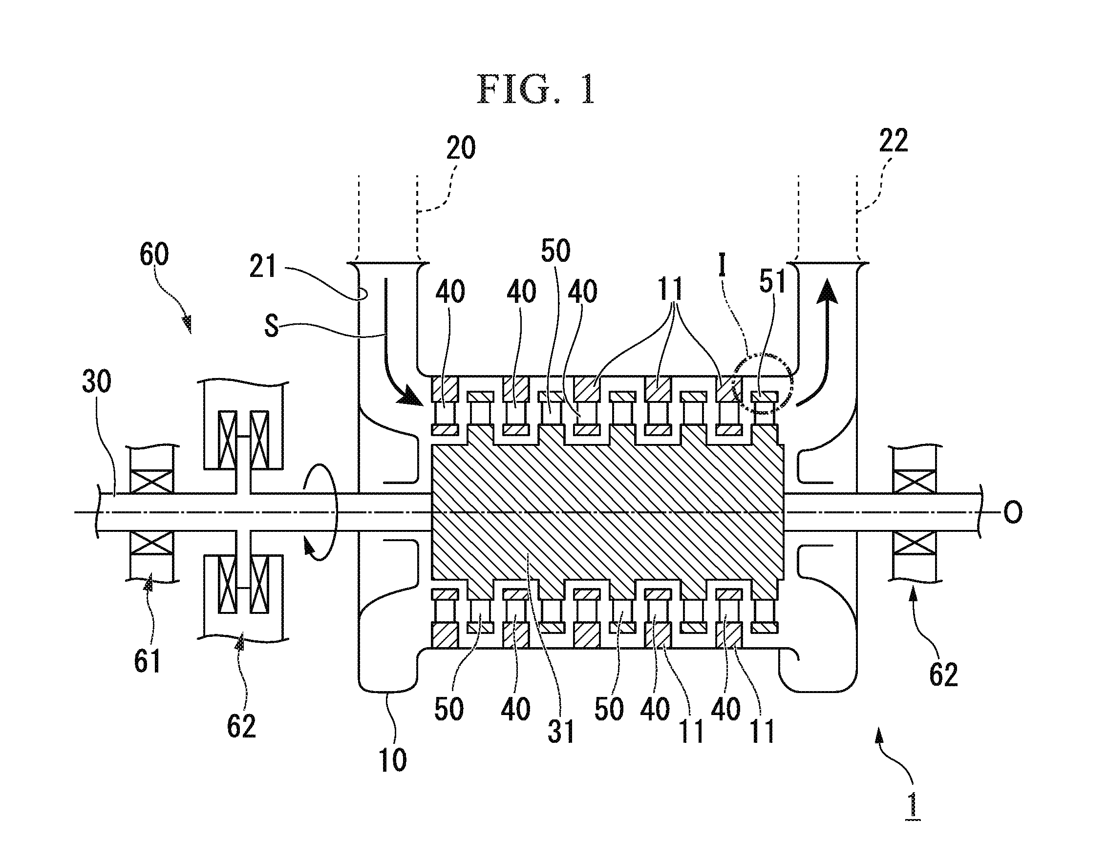
[0027]As shown in FIG. 1, a steam turbine 1 of the present embodiment is provided with a casing 10 (a stator), a rotating shaft 30 that is rotatably provided inward of the casing 10 and transmits a power to a machine such as a generator (not shown), a vane 40 that is held in the casing 10, a blade 50 that is provided on the rotating shaft 30, and a bearing portion 60 that rotatably supports the rotating shaft 30 about an axis thereof

[0028]Steam S is introduced from a main flow inlet 21 formed in the casing 10 via a steam supply pipe 20 connected to a steam supply source (not shown), and is discharged from a steam discharge pipe 22 connected to a downstream side of the steam turbine 1.

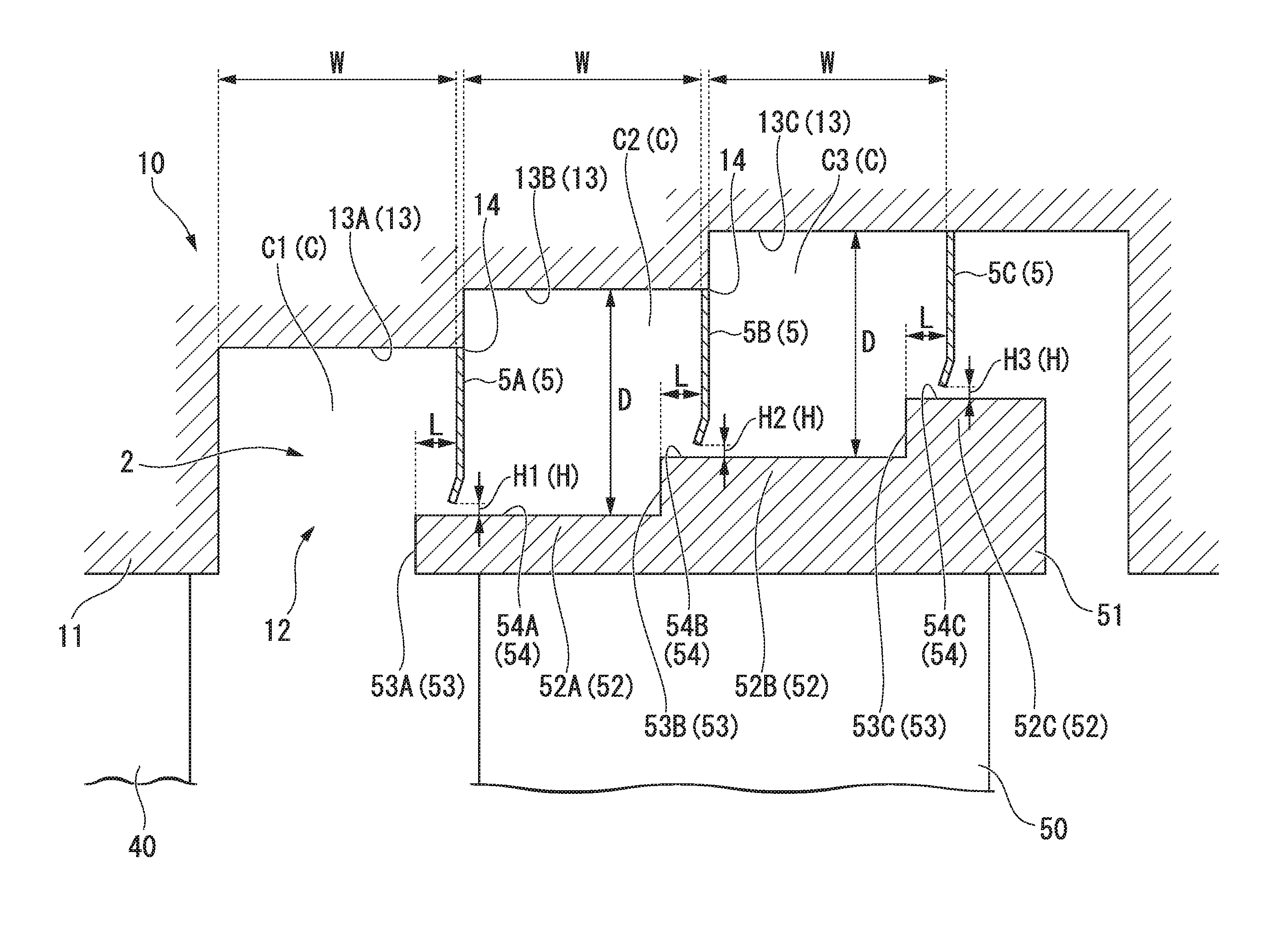
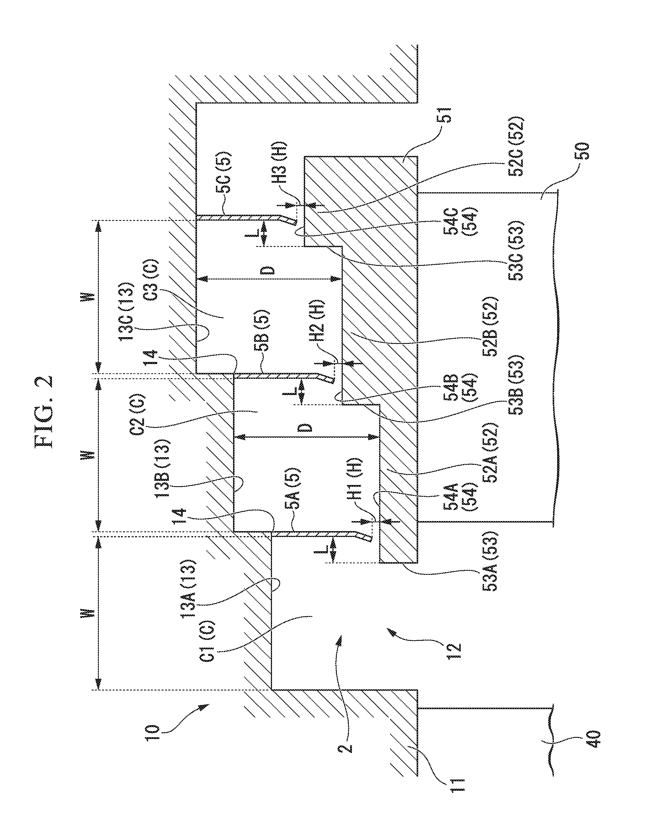
[0029]The casing 10 is formed as a flow path of the steam S and an internal space of the casing is hermetically sealed. On an inner wall surfa...


PUM


Abstract

A sealing structure that seals a clearance between an outer peripheral surface of a rotor and an inner peripheral surface of a stator. The sealing structure includes: a plurality of step portions that are provided on a first surface which is one of the outer peripheral surface of the rotor and the inner peripheral surface of the stator so as to be arranged in the axial direction, and that protrude from the first surface toward a second surface which is the other of the outer peripheral surface of the rotor and the inner peripheral surface of the stator; and a seal fin that is provided on the second surface, and that forms a small clearance between a corresponding peripheral surface of the step portions. A portion in the vicinity of a tip of the seal fin in the radial direction is inclined toward the upstream side.

Description

TECHNICAL FIELD[0001]The present invention relates to a sealing structure that seals a clearance between a rotor and a stator, and a rotary machine provided therewith.[0002]Priority is claimed on Japanese Patent Application No. 2014-042142 filed Mar. 4, 2014, the contents of which are incorporated herein by reference.BACKGROUND ART[0003]As it is well known, as a type of steam turbine which is a rotary machine, there is a rotary machine including a casing, a shaft body (rotor) rotatably provided inside the casing, a plurality of vanes which are fixedly disposed on an inner periphery of the casing, and a plurality of blades provided radially on the shaft body at a downstream side of the plurality of vanes. In the case of an impulse turbine among such steam turbines, pressure energy of steam (fluid) is converted to kinetic energy by the vanes, and the kinetic energy is converted into rotational energy (mechanical energy) by the blades. Further, in the case of a reaction turbine, pressu...

Claims


Application Information

Patent Timeline
IPC IPC(8): F01D11/08F01D9/02F01D5/02
CPCF01D11/08F05D2220/31F01D9/02F01D5/02F01D5/225F01D11/02F05D2250/314F16J15/3264F01D11/12
Inventor MATSUMOTO, KAZUYUKIKUWAMURA, YOSHIHIROOYAMA, HIROHARUTANAKA, YOSHINORI
Owner MITSUBISHI POWER LTD
Why Eureka
Try Eureka