Pneumatic-Type Precision Annular Workpiece Inner Positioning Surface Clamping Device

a technology of annular workpieces and clamping devices, which is applied in the direction of mechanical equipment, chucks, manufacturing tools, etc., can solve the problems of increased friction during adjustment, inability to ignore ultra-precision parts, and inconvenient use of axial clamping, so as to simplify mechanical design and maintenance, reduce non-linear effects of uneven force, and facilitate operation. speed adjustment

Active Publication Date: 2016-11-24
HARBIN INST OF TECH
View PDF11 Cites 21 Cited by
  • Summary
  • Abstract
  • Description
  • Claims
  • Application Information

AI Technical Summary

Benefits of technology

[0012]It uses air as the medium to realize centralized gas supply by utilizing the compressibility of the air, thereby significantly simplifying mechanical design and maintenance; application of force is uniform, so non-linear effects caused by uneven force is reduced; intelligent control of operating speed can be achieved, and the input and output torques and the operating speed can be easily adjusted; the device has a simple structure, light weight, low manufacturing cost, high reliability and long service life, is easy in installation and maintenance, and can realize buffering.

Problems solved by technology

Yet, this program still has a drawback that its use of axial clamping is not suitable for clamping thin-walled cylindrical workpieces.
Yet, the problem of the program lies in that it uses an outside chuck and the clamping member may cause deformation of the contour outline of the clamped object, which cannot be ignored for ultra-precision parts.
Such structure is characterized in that it has high reliability and tightening of the chuck can be easily adjusted by hand, but the problem lies in that its structure is a little bit complex, so it is necessary to correspondingly enlarge the device in proportion when clamping large workpieces, resulting in increased friction during adjustment, which is not conducive to assembly and clamping.
Generally, the traditional three-jaw chuck and multi-jaw chuck clamping mechanisms may cause irreparable damages to the surface of the workpiece during assembly due to their own natural defects of applying uneven forces to the workpiece.
In addition, with the constant emerge of more and more large and ultra-large annular workpieces, volume of the traditional three-jaw chuck and multi-jaw chuck clamping mechanisms should be enlarged as the outer diameter of the circular ring increases, which provides them less advantage in terms of economic cost and limits the designers in designing large annular workpieces at the same time.

Method used


Image

  • Pneumatic-Type Precision Annular Workpiece Inner Positioning Surface Clamping Device
  • Pneumatic-Type Precision Annular Workpiece Inner Positioning Surface Clamping Device

Examples


Embodiment Construction

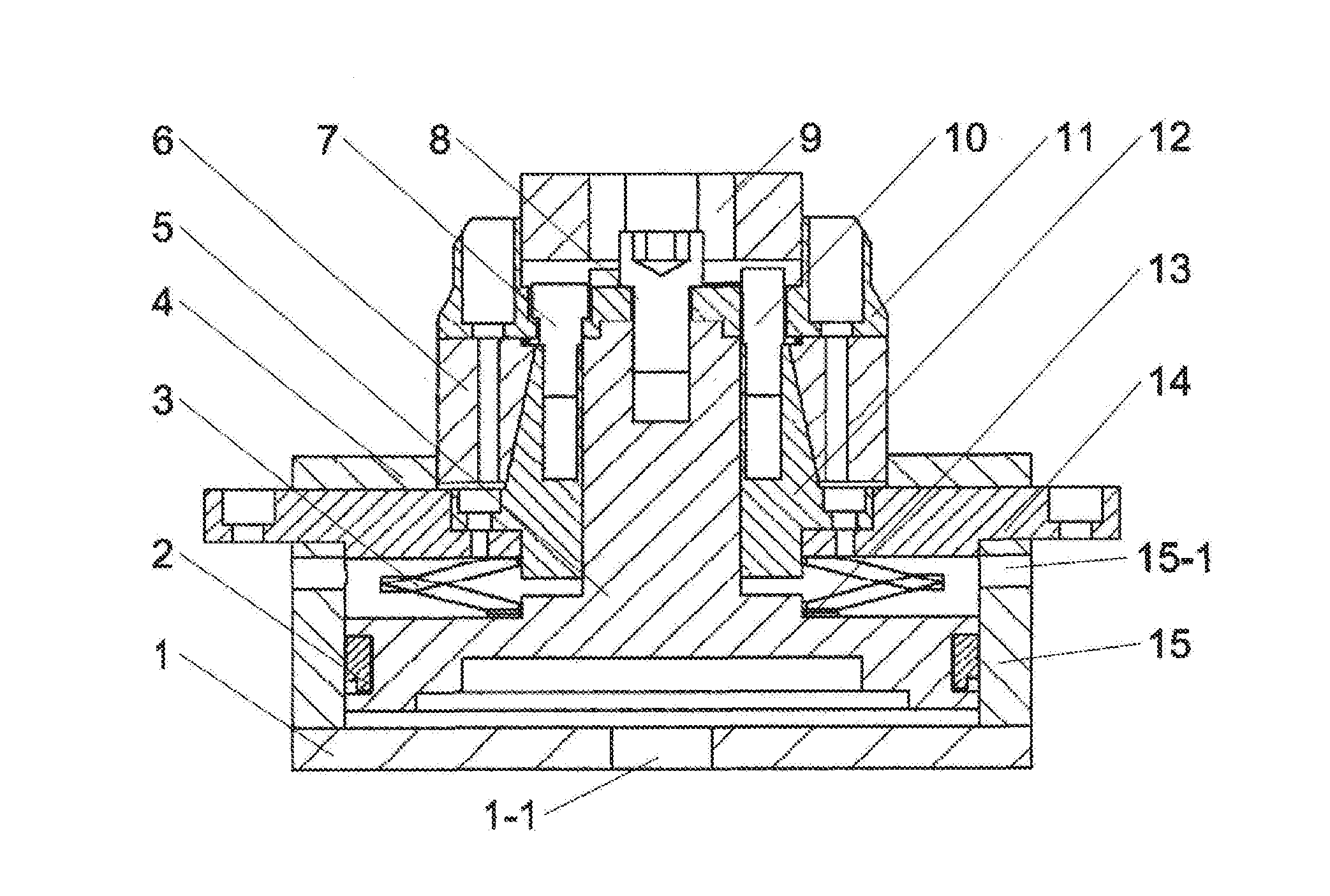
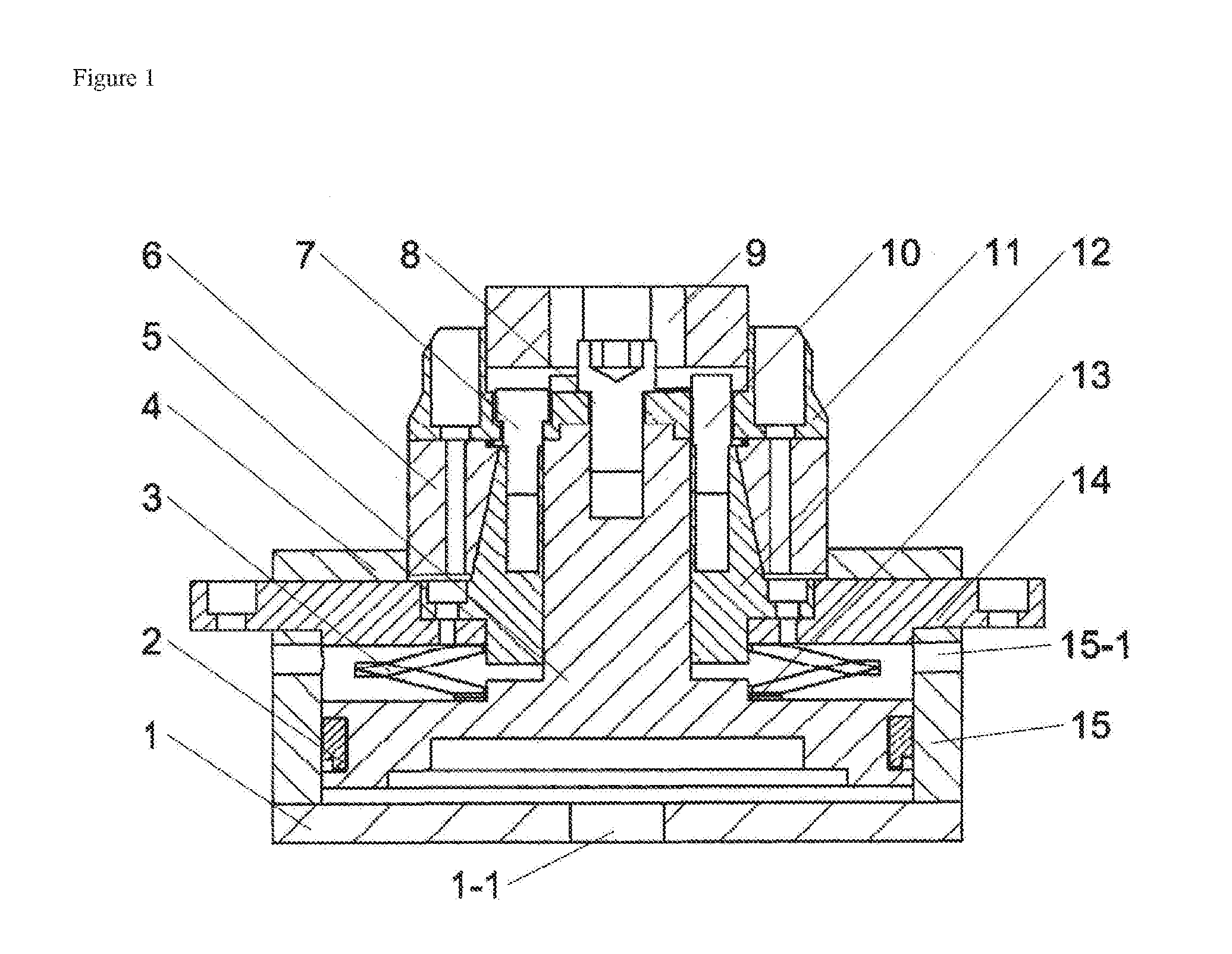
[0015]Specific embodiments of the present invention are further described in detail with reference to the drawing.

[0016]A pneumatic-type precision annular workpiece inner positioning surface clamping device, characterized in that, an upper plate 14 and a lower plate 1 are tightly fixed onto the upper and lower end surfaces of a cylinder body 15, respectively; a wedge-shaped block 12 is fixed on the upper plate 14, forming a closed chamber in the cylinder body 15; a rod portion of a piston assembly 5 is inserted into a central hole of the wedge-shaped block 12, and the piston portion of the piston assembly 5 is provided in a closed chamber formed in the cylinder body 15, dividing the closed chamber into an upper chamber and a lower chamber which are completely separated from each other; a seal ring 2 is provided on the outer circular surface of the piston portion of the piston assembly 5; a disc spring 3 is sleeved on the piston assembly 5 and is located in the upper chamber of the c...


PUM


Abstract

A pneumatic-type precision annular workpiece inner positioning surface clamping device, wherein a rod portion of a piston assembly (5) is inserted into a central hole of the wedge-shaped block (12), and the piston portion of the piston assembly (5) is located in a closed chamber of a cylinder body (15); a disc spring (3) is sleeved on the piston assembly (5); an air intake hole (1-1) is provided in the lower plate (1), an air vent hole (15-1) is provided at the upper portion of the cylinder body (15); and an elastic hinge block (6) is sleeved outside the wedge-shaped block (12). The pneumatic-type precision annular workpiece inner positioning surface clamping device has a simple structure, high reliability and strong adaptability.

Description

TECHNICAL FIELD[0001]The present invention belongs to a workholding apparatus, and mainly relates to a clamping device for a precision annular workpiece in the field of equipment manufacture.BACKGROUND ART[0002]In the fields of ultra-precision measurement and testing and ultra-precision machining, a clamping device with high speed, stability and precise positioning is the fundamental guarantee to precision measurement and aviation engine assembly. At present, with the progress in material science, as well as the increase in precision levels of ultra-precision measuring instruments and ultra-precision manufacturing equipment, designs of high-precision annular workpiece are applied more and more widely, and the devices used in the machining process becomes a basis for ensuring the machining precision.[0003]Hefei University of Technology proposed a swing rod axial buckling chuck (Swing Rod Axial Buckling Chuck; Patent Application No.: CN 201210212982.1). The program is designed with a ...

Claims


Application Information

Patent Timeline
Patent Type & Authority Applications(United States)
IPC IPC(8): B23B31/40B23Q3/08
CPCB23B31/402B23Q2703/10B23Q3/08B23B31/204Y10T279/1012Y10T279/1258
Inventor TAN, JIUBINYANG, YUANYUANWANG, LEIZHAO, BO
Owner HARBIN INST OF TECH
Why Eureka
Try Eureka