Dynamic exterior aircraft light unit and method of operating a dynamic exterior aircraft light unit

a technology of aircraft light and dynamic structure, which is applied in the direction of lighting and heating equipment, using reradiation, instruments, etc., can solve the problems of reducing the awareness of the remainder of the environment by the pilot, the inability of the pilot to accurately and favourably operate the lights, and the inherent risk of the pilot disregarding the remainder of the helicopter environment. , to achieve the effect of accurate light detection and reducing the sensitivity requirements of the photo detector

Active Publication Date: 2016-11-24
GOODRICH LIGHTING SYST
View PDF5 Cites 16 Cited by
  • Summary
  • Abstract
  • Description
  • Claims
  • Application Information

AI Technical Summary

Benefits of technology

[0022]According to a further embodiment, the exterior aircraft light unit further comprises a photo detector lens, associated with the photo detector, the photo detector lens directing light from an expected reflection sector towards the photo detector, the expected reflection sector having an opening angle of between 20° and 40° in a horizontal direction and between 10° and 20° in a vertical direction and the expected reflection sector being directed downwards at a d

Problems solved by technology

With the given large number of different lights and an ever increasing adaptation of the lights to particular operating situations, the burden on the pilot and/or air crew for correctly and favourably operating the lights has become quite significant.
Based on this knowledge, it is possible that the control unit interprets a particular approach angle to be not a glide angle, because the approa

Method used


Image

  • Dynamic exterior aircraft light unit and method of operating a dynamic exterior aircraft light unit
  • Dynamic exterior aircraft light unit and method of operating a dynamic exterior aircraft light unit
  • Dynamic exterior aircraft light unit and method of operating a dynamic exterior aircraft light unit

Examples


Embodiment Construction

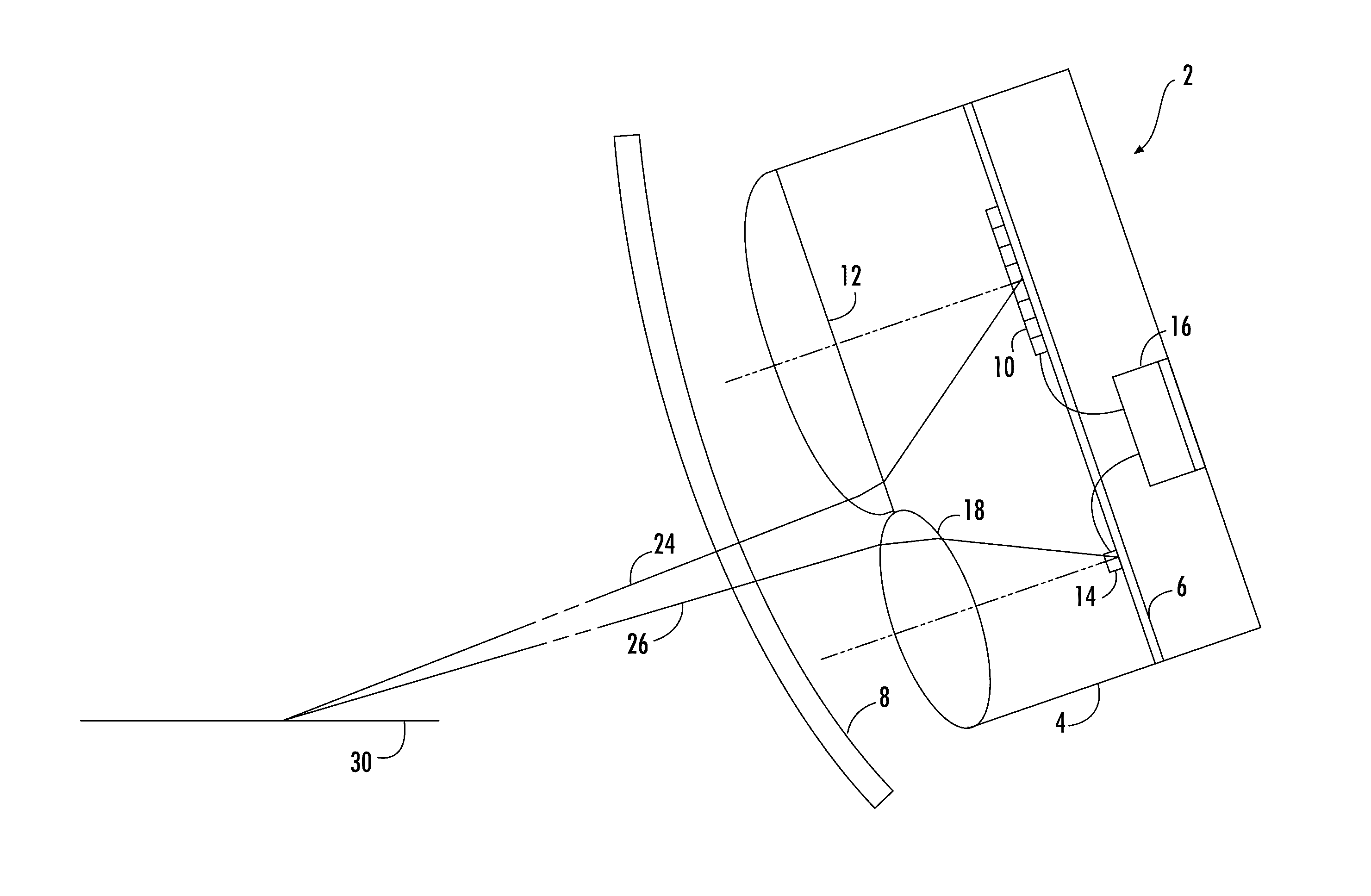
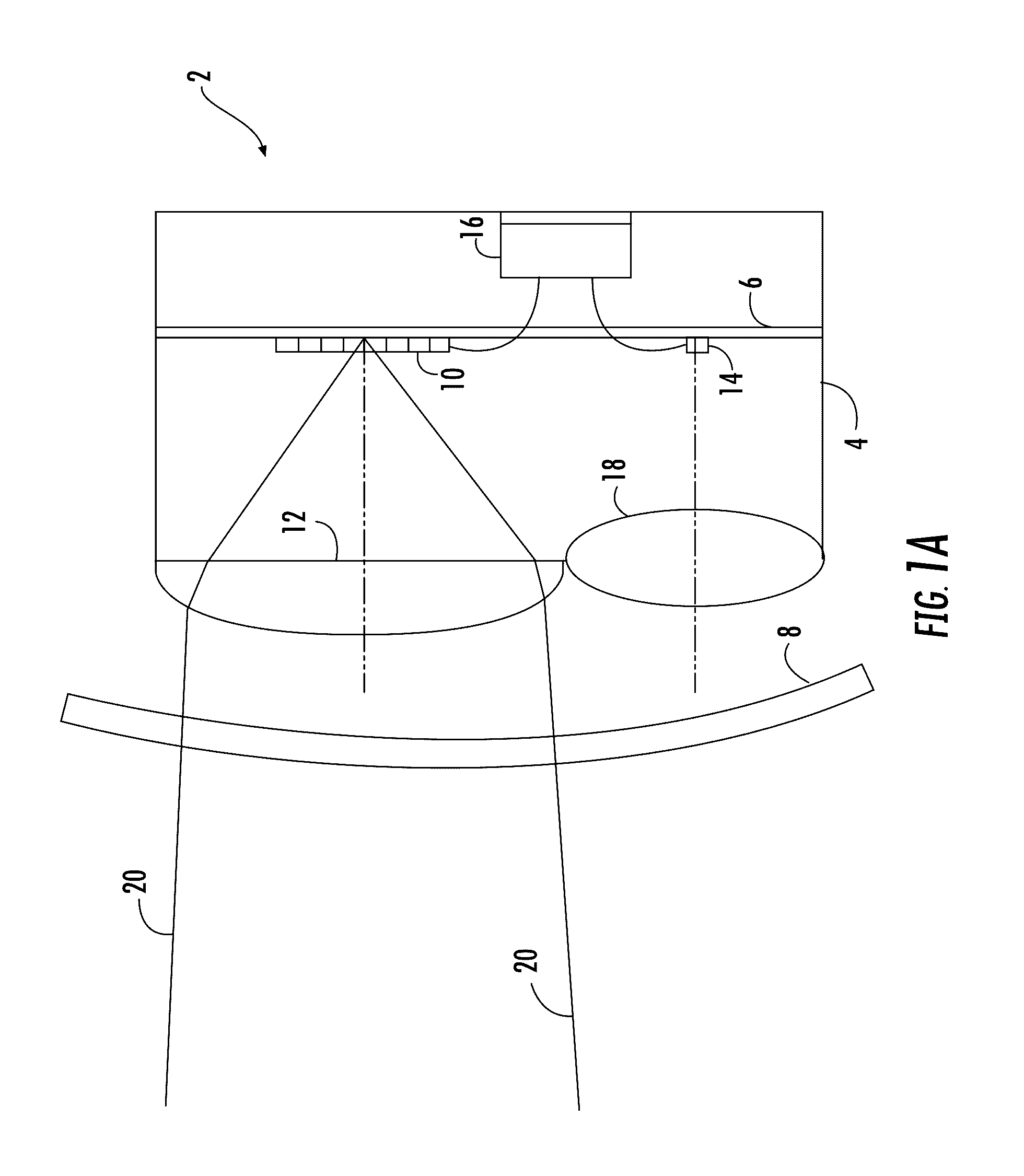
[0032]FIG. 1a shows an exemplary embodiment of an air plane landing light 2 in accordance with the invention. The air plane landing light 2 is a particular embodiment of a dynamic exterior aircraft light unit in accordance with exemplary embodiments of the invention. Accordingly, it is also referred to as an exterior aircraft light unit 2.

[0033]The exterior aircraft light unit 2 is shown in a cross-sectional, schematic view in the exemplary embodiment of FIG. 1a. The exterior aircraft light unit 2 comprises a housing 4 and a mounting plate 6, to which most of the other elements of the exterior aircraft light unit 2 are mounted. The mounting plate 6 is disposed within the interior of the housing 4. The exterior aircraft light unit 2 further comprises a lens cover8, which forms the outermost portion of the exterior aircraft light unit 2 and through which the exterior aircraft light unit 2 emits light.

[0034]The exterior aircraft light unit 2 comprises a plurality of LEDs 10. In particu...


PUM


Abstract

A dynamic exterior aircraft light unit includes a plurality of LEDs, with at least two subsets of the plurality of LEDs being separately, an optical system for transforming light output from the plurality of LEDs into at least two light emission distributions, a control unit for controlling the plurality of LEDs, and a photo detector arranged to detect light, emitted by the dynamic exterior aircraft light unit as part of the at least two light emission distributions and reflected by the aircraft environment, and configured to output a light detection signal.

Description

FOREIGN PRIORITY[0001]This application claims priority to European Patent Application No. 15 168 387.7 filed May 20, 2015, the entire contents of which is incorporated herein by reference.TECHNICAL FIELD[0002]The present invention is in the field of exterior aircraft lighting. In particular, the present invention is in the field of exterior aircraft light units that have multiple modes of operation.BACKGROUND OF THE INVENTION[0003]Almost all aircrafts are equipped with exterior lights. For example, large passenger air planes have a wide variety of exterior lights. Examples are navigation lights or position lights, beacon lights, anti-collision lights or strobe lights, wing lights, taxi lights, landing lights, runway turnoff lights, etc. Exemplary helicopters usually have landing lights, search lights, etc. With the given large number of different lights and an ever increasing adaptation of the lights to particular operating situations, the burden on the pilot and / or air crew for cor...

Claims


Application Information

Patent Timeline
IPC IPC(8): H05B37/02G01S17/02B64D47/04G01S17/42H05B33/08B64D47/06F21W107/30G01S17/04G01S17/10H05B44/00
CPCH05B37/0227H05B33/0854G01S17/026B64D47/04G01S17/42B64D47/06B60Q1/247F21S43/14F21V19/001F21V23/0442F21W2107/30B60Q1/0023B60Q1/085B60Q1/18F21S41/663F21S41/25F21S41/153G01S17/10G01S7/4802G01S7/4815G01S17/58G01S17/88H05B45/12H05B47/11Y02B20/40G01S17/04
Inventor SCHOEN, CHRISTIANHESSLING-VON HEIMENDAHL, ANDREJHA, ANIL KUMAR
Owner GOODRICH LIGHTING SYST
Why Eureka
Try Eureka