
Nickel phosphides electrocatalysts for hydrogen evolution and oxidation reactions

a technology of phosphides and electrocatalysts, which is applied in the direction of electrolyte coatings, cell components, physical/chemical process catalysts, etc., can solve the problems of high capital costs, high electrical losses, and industrial electroly

Active Publication Date: 2016-12-08
RUTGERS THE STATE UNIV
View PDF1 Cites 12 Cited by
  • Summary
  • Abstract
  • Description
  • Claims
  • Application Information

AI Technical Summary

Benefits of technology

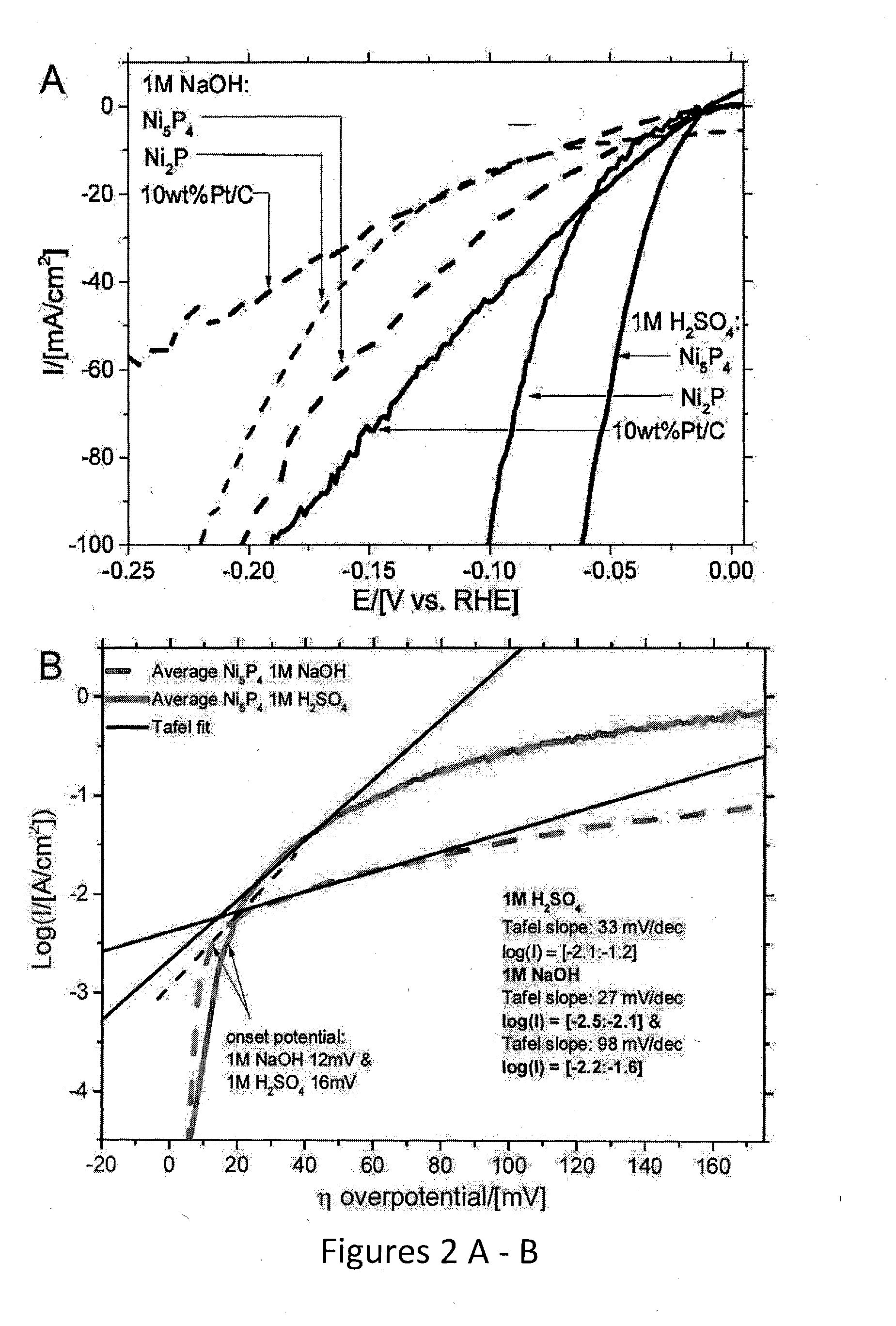
The present invention provides a new method for generating hydrogen gas from water using a conductive support substrate with nanocrystals of Ni5P4 as the catalyst. The nanocrystals are able to interact with water molecules and reduce them to hydrogen cations, which can then be converted to hydrogen gas through an electrolysis reaction. The nanocrystals have a grain size of about 5 to 1800 nm, preferably about 5 to 1000 nm. The invention also provides a new method for reducing hydrogen cations to form hydrogen gas using a free catalyst. The nanocrystals are able to interact with hydrogen cations and reduce them to hydrogen gas. The electrochemical cell includes a chamber containing an aqueous electrolyte and a conductive support substrate with nanocrystals of Ni5P4 as the catalyst. The technical effects of this invention include improved efficiency and selectivity for hydrogen gas production, as well as reduced costs and improved stability of the catalyst.

Problems solved by technology

Although H2 can be produced by electrochemical water splitting, industrial electrolyzers, even where inexpensive electricity is available, operate with high electrical losses due to inefficient catalysts (50-65%) or have high capital costs.
Commercial alkaline electrolyzers rely on Ni electrodes that have low efficiencies and degrade over time, but this limitation has been accepted due to the relatively low cost of Ni.
However, Pt is a scarce element (106 times more scarce than Fe) and very expensive.

Method used


Image

  • Nickel phosphides electrocatalysts for hydrogen evolution and oxidation reactions
  • Nickel phosphides electrocatalysts for hydrogen evolution and oxidation reactions
  • Nickel phosphides electrocatalysts for hydrogen evolution and oxidation reactions

Examples


example 1

Synthesis of Ni5P4 Nanoparticles

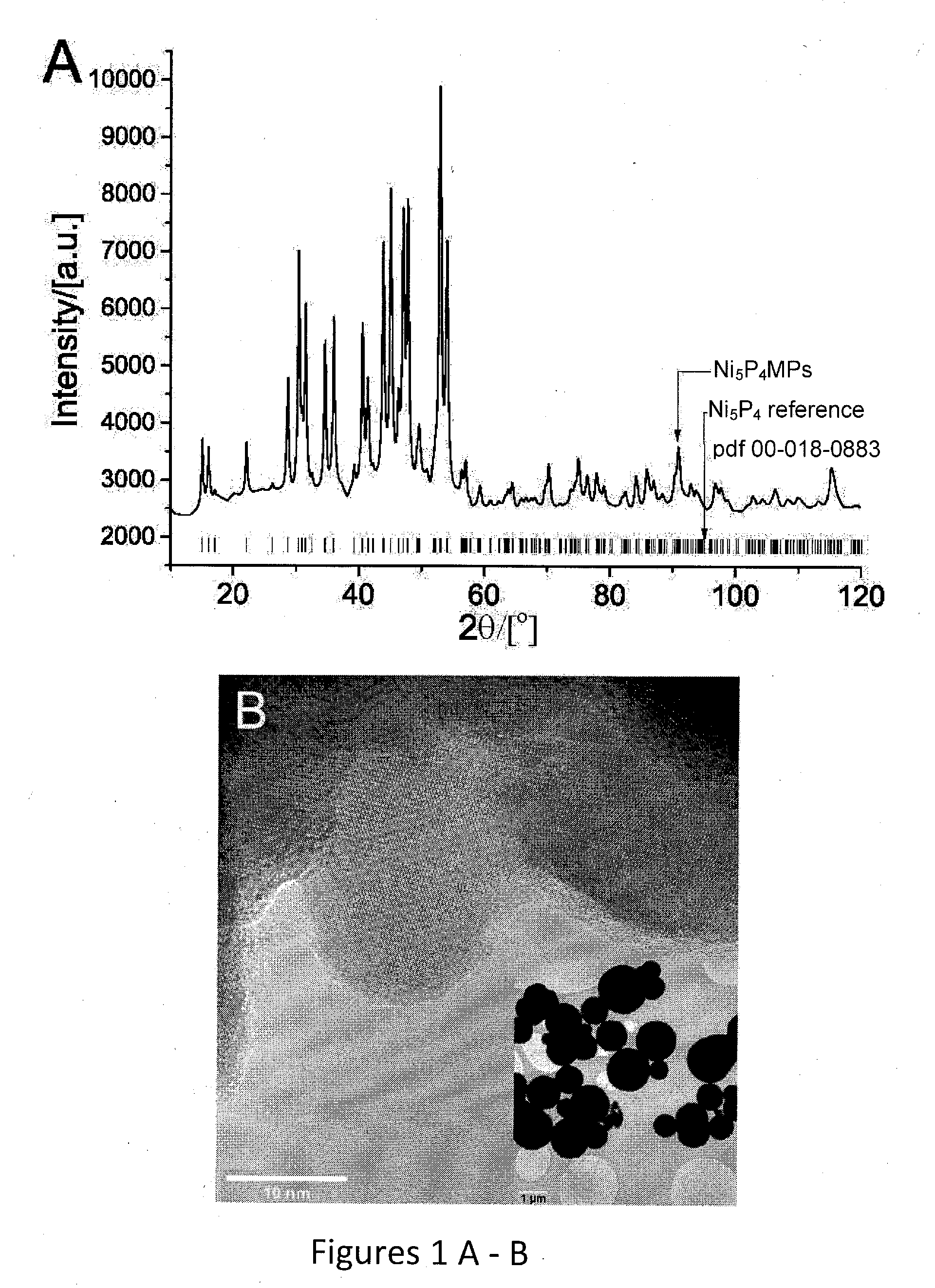
[0048]Using a solvothermal synthesis route adapted from K. Aso et al. (Inorganic Chemistry, 2011, 50, 10820-10824) Ni5P4 was synthesized as phase pure nanocrystals (Ni5P4 NPs). About 0.385 g Ni(acetylacetonate, acac)2.xH2O (Sigma-Aldrich) was placed in a 3-necked flask together with about 2.5 g tri-n-octylphosphine oxide. TOPO (Strem Chemicals). The flask was connected to a condenser in one port, a Schlenk line in the other, and corked in the third. The condenser was connected to a silicone oil bubbler venting into a fumehood.

[0049]The flask was degassed under vacuum and then refilled with high purity Ar (Air-liquid). A flow of Ar was established through the flask before adding 10 ml of tri-n-octylphosphine, TOP (Strem Chemicals) wider an Ar blanket. The solution was left under Ar flow for approximately 20 minutes to remove any oxygen. The Ar flow was adjusted to a slow rate 1 bubble per second and the flask was then placed on a pre-heated sand bath a...

example 2

Synthesis of Ni2P Nanoparticles

[0051]Ni2P NPs were synthesized by the procedure published by Muthuswamy et al. (ACS Nano, 2011, 5, 2402-2411). About 1.03 g Ni(acac)2.xH2O was placed in a 3-neck flask together with 10 ml n-octylether and 4.6 g oleylamine. The flask was connected to a condenser and Schlenck line as for the procedure for Ni5P4 nanoparticles described above. The flask was evacuated until bubbling subsided (about 10-15 min), and then a flow of Ar was established and 10.2 ml TOP was added under an Ar blancket. The flask was then evacuated anew and heated lightly by placing it 1 cm above a sand bath preheated to 230° C. The reagents dissolved under bubbling (water removal) and formed a deep green clear solution (approximately 30-60 min). Once all of the Ni(acac)2 had dissolved and bubbling had subsided, the flask was filled with Ar and a slow Ar flow was established. The flask was placed in the preheated sand bath for 1 hour (at 230° C.) during which a dark brown solution ...

example 3

Electrode Preparation of Ni5P4, Ni,P, and Pt

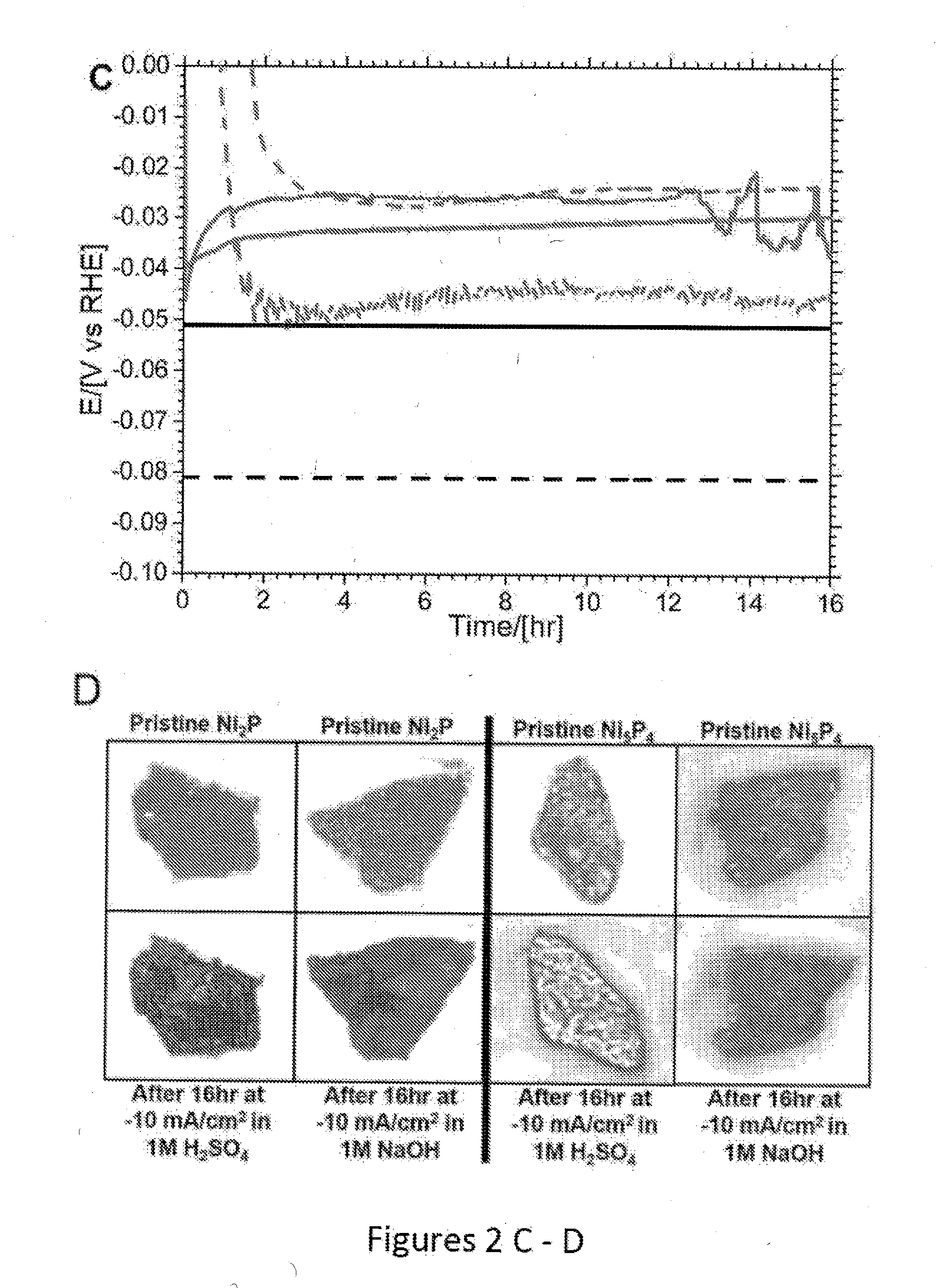
[0053]Due to the tendency of Ni5P4 to convert into Ni2P upon heating above 350° C., the procedure used by Popczun et al. (Journal of the American Chemical Society, 2005, 127, 14871-14878) for thick coatings of Ni2 P nanoparticles could not be applied here; instead 50 mg of each catalyst was pressed into a pellet and bonded to a titanium film electrode via silver paint and sealed in non-conducting epoxy. 50 mg of catalyst was pressed in a 6 mm die allowing the pressure to equilibrate, at 2 tons for 10-15 min then increasing the pressure up to the final 4.5 ton. This pressure was held for 16 hours. After removing from the die the pellet was quartered and each piece attached to 6 mm Ti-foil with Ag-paint (SPI supplies). After drying, the Ti-foil -pellet was attached to a Cu-wire (curled into a spiral in one end) with Ag-paint. When the Ag-paint had cured (overnight at room temperature or 10 min at 120° C)., The Cu-wire was threaded through a ...


PUM

PropertyMeasurementUnit
grain sizesaaaaaaaaaa
turnover frequencyaaaaaaaaaa

Abstract

Disclosed are cathodes comprising a conductive support substrate having a catalyst coating including Ni5P4 nanocrystals. The conductive support substrate is capable of incorporating a material to be reduced, such as water or hydrogen cations. Also disclosed are methods for generating hydrogen gas from water via an electrolysis reaction or from the reduction of hydrogen cations, wherein the catalyst is part of a conductive support within a cathode, including (a) placing an anode and the inventive cathode in an electrolyte, (b) placing the anode and cathode in conductive contact with an external source of electricity, (c) providing a source of water to the cathode, and (d) using the external source of electricity to drive an electrolysis reaction at the cathode, whereby the hydrogen gas is generated from water. In certain embodiments, the reaction uses a free catalyst, wherein the catalyst is placed in proximity to the cathode.

Description

FIELD OF INVENTION[0001]The present invention relates to novel electrocatalysts for hydrogen generation by electrolysis of water and hydrogen oxidation for electricity generation, particularly nanocrystalline Ni5P4, and methods of reversible hydrogen electrocatalysis.BACKGROUND[0002]The environmental impact of finite fossil energy resources has spurred ever increasing research into renewable energy resources (e.g., solar and wind electricity and solar fuels). These intermittent energy sources entail a need for storage and conversion. Energy can be stored safely and conveniently as chemical bonds, and hydrogen (H2) is one such possible energy carrier. H2 is also a valuable bulk chemical currently produced at large-scale (˜63 Mton / yr3) from natural gas. A renewable source of H2 would thus not only be useful for storing intermittent renewable energy, but also serve as a major chemical feedstock.[0003]Although H2 can be produced by electrochemical water splitting, industrial electrolyze...

Claims


Application Information

Patent Timeline
Patent Type & Authority Applications(United States)
IPC IPC(8): C25B11/04H01M8/1246C25B9/10H01M4/90C25B1/04C25B1/00C25B9/23
CPCC25B11/0447C25B1/04C25B1/003H01M2008/1293C25B11/0405H01M4/9075H01M8/1246C25B9/10B01J23/755H01M4/90C25B11/04Y02E60/36Y02E60/50C25B9/40C25B1/55C25B9/23C25B11/051C25B11/075B01J27/1853B01J31/18
Inventor DISMUKES, G. CHARLESLAURSEN, ANDERSGREENBLATT, MARTHA
Owner RUTGERS THE STATE UNIV
Learn More