Measurement device for a laser processing system and a method for performing position measurements by means of a measurement beam on a workpiece

a laser processing system and measurement beam technology, applied in the direction of measurement devices, laser beam welding apparatus, instruments, etc., can solve the problems of reducing the efficiency of scanning operation, limiting the number of measurement points in a certain measurement area, and requiring relative large circular paths to be provided, so as to facilitate the polygonal mirror and save costs

Active Publication Date: 2016-12-08
LESSMULLER LASERTECHN
View PDF9 Cites 43 Cited by
  • Summary
  • Abstract
  • Description
  • Claims
  • Application Information

AI Technical Summary

Benefits of technology

[0020]One object of the present invention is to make available a measurement device, a device having a measurement device and a method which enables efficient performance of position measurements on a workpiece. In particular, an improved scanning efficiency is to be achieved through the present invention.
[0068]According to one refinement of the invention at least one part of the measurement device may be permanently connected to the processing device. In particular, a beam splitter, a measurement arm and a reference arm of the measurement device may be fixedly connected to the processing device. These components can be thereby carried along with the processing device so that the required lengths of the optical fibers of the measurement arm and of the reference ram can be minimized. This reduces possible interfering influences and improves the quality of the measurement process.

Problems solved by technology

This has the disadvantage that a relatively large radius of the circular path must be provided to detect regions which are disproportionately a great distance in front of or behind a processing position with respect to a main processing path.
This reduces the efficiency of a scanning operation and also limits the number of measurement points in a certain measurement area, for example, in front of or behind the processing position.
However, the construction and fabrication of three-dimensional free-form surfaces on a polygon / polygonal body are complex and are associated with a high technical and financial outlay.
Furthermore, with the arrangement described here the scanning path of the measurement beam on the workpiece is structurally determined by the shape of the free-form surfaces of the polygonal mirror and cannot be varied during the measurement operation.
This reduces scanning efficiency and thus also the efficiency of the monitoring process.

Method used


Image

  • Measurement device for a laser processing system and a method for performing position measurements by means of a measurement beam on a workpiece
  • Measurement device for a laser processing system and a method for performing position measurements by means of a measurement beam on a workpiece
  • Measurement device for a laser processing system and a method for performing position measurements by means of a measurement beam on a workpiece

Examples


Embodiment Construction

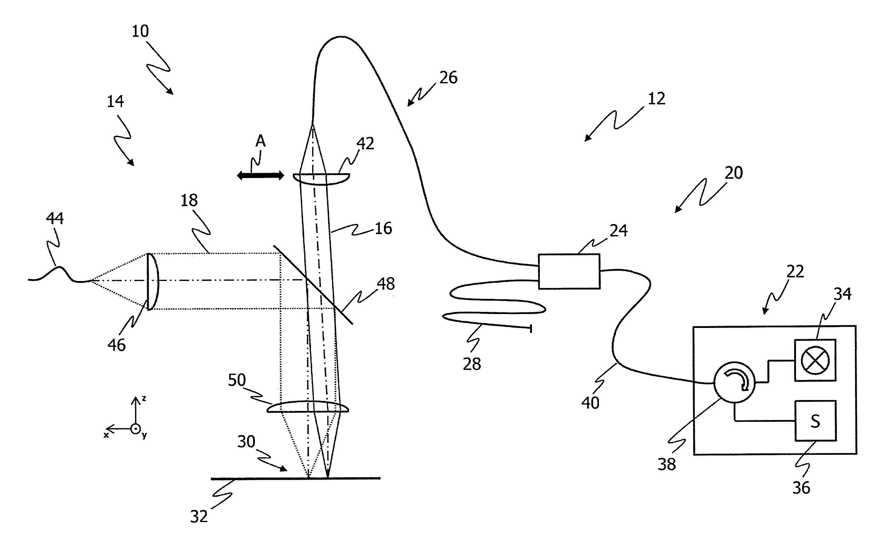
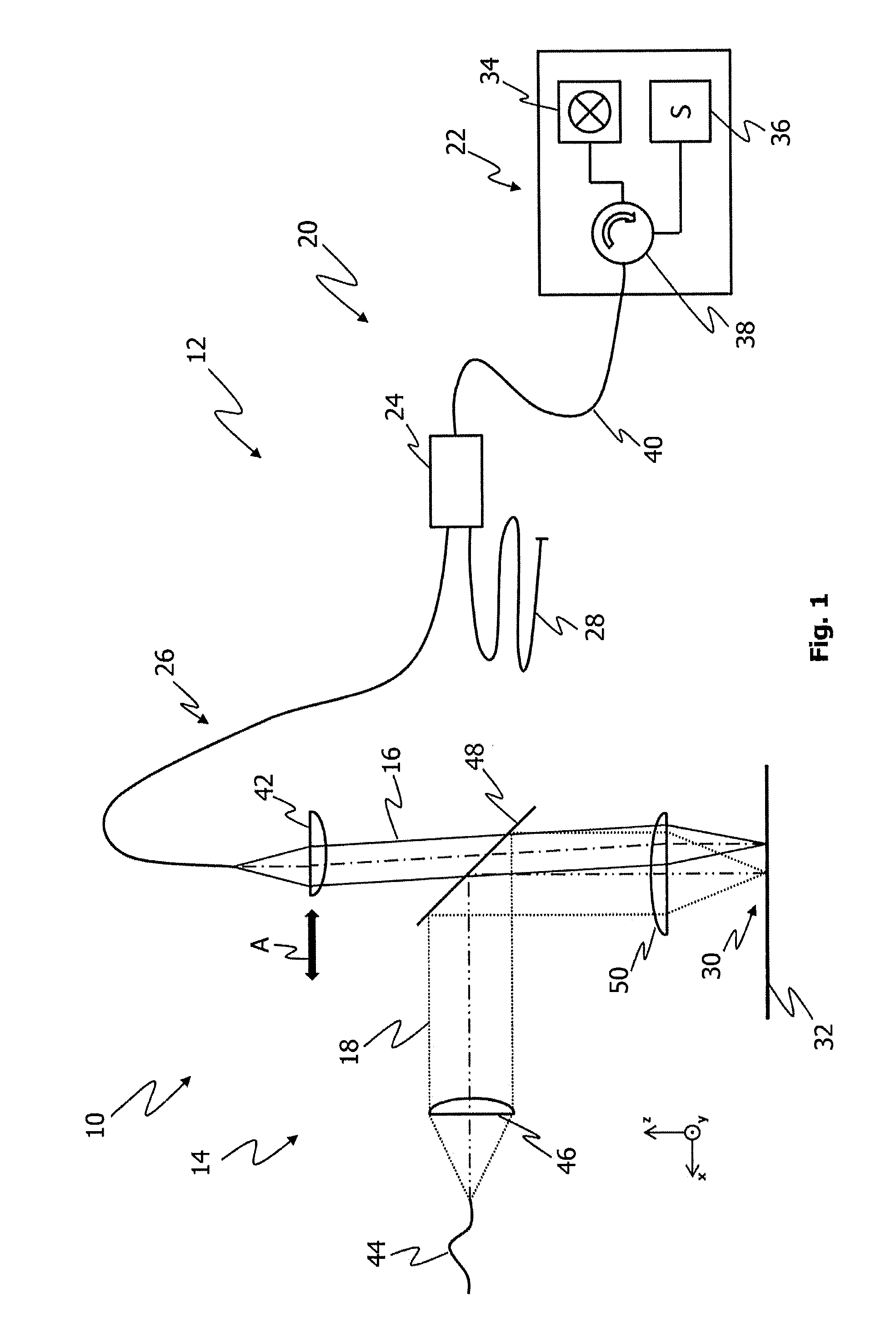
[0099]FIG. 1 shows a device according to the invention in a first embodiment, which is labeled as 10 in general. The device 10 includes a measurement device 12 and a processing device 14. The measurement device 12 is coupled to the processing device 14 so that a measurement beam 16 of the measurement device 12 is superimposed at least partially on a processing beam 18 of the processing device 14. The measurement device 12 includes an optical coherence tomograph 20 (OCT) with an OCT measurement device 22 which is connected to a measurement arm 26 and a reference arm 28 by means of a beam splitter 24.

[0100]The beam splitter 24 of the optical coherence tomograph 20 is permanently connected to the processing device 14 (not shown). Therefore, the beam splitter 24, the transport fiber of the measurement arm 26 and of the reference arm 28 are guided essentially jointly with the processing device 14 along a main processing path 30 on the workpiece 32. This has the advantage that the require...


PUM

PropertyMeasurementUnit
angleaaaaaaaaaa
wavelengthaaaaaaaaaa

Abstract

The invention relates to a measurement device for a laser processing system, for carrying out position measurements by means of a measurement beam on a workpiece, which is intended for processing by means of a high energy processing beam, which can be moved relative to the workpiece along a predetermined main processing path. The measurement device can be coupled to a processing device and includes an optical coherence tomograph. The measurement device is equipped to shift the measurement beam on the workpiece in the direction of the main processing path in at least one first measurement position and one second measurement position in order to scan measurement positions transversely to the direction of the main processing path in the measurement positions.

Description

FIELD OF THE INVENTION[0001]The present invention relates to a measurement device for a laser processing system for performing position measurements by means of a measurement beam on a workpiece which is provided for processing by means of a high-energy processing beam, which is movable in a processing direction along a predetermined main processing path relative to the workpiece, wherein the measurement device can be coupled to a processing device and includes an optical coherence tomograph having a measurement beam source for generating the measurement beam, and wherein the measurement device is equipped to shift the measurement beam onto the workpiece within a predetermined measurement range.BACKGROUND OF THE INVENTION[0002]In known devices, a method known as optical coherence tomography (OCT) is increasingly being used for monitoring (laser) processing operations. This method is based on the fundamental principle of interference of light waves and the resulting effects. Optical ...

Claims


Application Information

Patent Timeline
Patent Type & Authority Applications(United States)
IPC IPC(8): G01B11/14B23K26/03G01B9/02
CPCG01B11/14B23K26/032G01B9/02091B23K26/044G01B2290/65
Inventor LESSMUELLER, ECKHARDTRUCKENBRODT, CHRISTIANWERNER, KONSTANTIN
Owner LESSMULLER LASERTECHN
Why Eureka
Try Eureka