Corrosion detection circuit for circuit board and motor drive having the same
a corrosion detection and circuit board technology, applied in the direction of instruments, measurement devices, scientific instruments, etc., can solve the problems of difficulty and cost increase, and achieve the effect of increasing resistance value and cos
- Summary
- Abstract
- Description
- Claims
- Application Information
AI Technical Summary
Benefits of technology
Problems solved by technology
Method used
Image

Examples
first embodiment
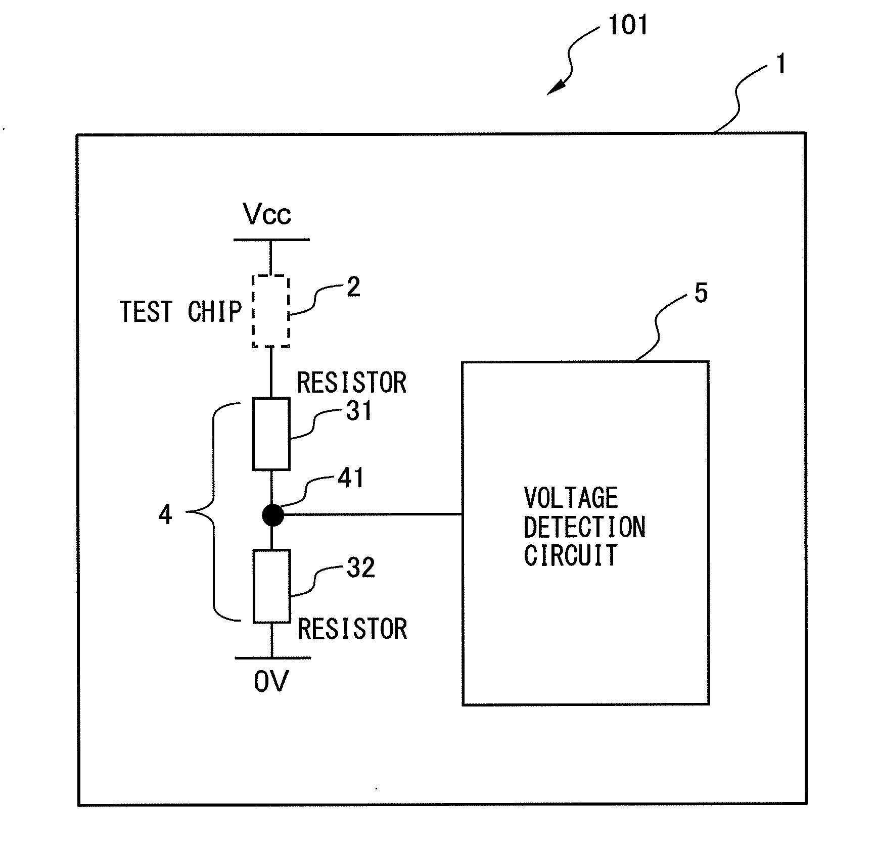
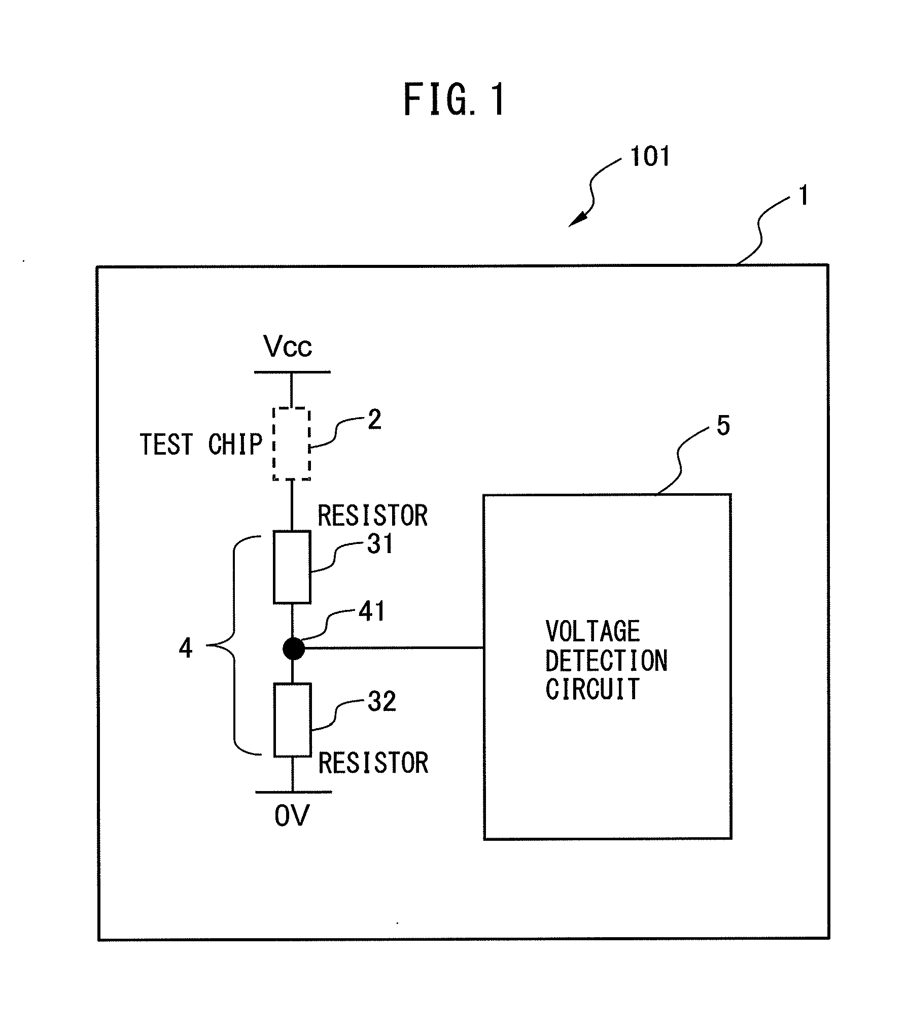
[0024]A corrosion detection circuit according to a first embodiment of the present invention will be described. FIG. 1 is a block diagram of the corrosion detection circuit according to the first embodiment of the present invention. A corrosion detection circuit 101 according to the first embodiment of the present invention includes an insulating board 1, a test chip 2 that is mounted on the surface of the insulating board 1 and has a corrodible metal, a plurality of resistors 31 and 32 having higher resistance values than the test chip 2 after a change due to environmental factors including contact with the test chip 2 or the adhesion of dust to the test chip 2, and a voltage detection circuit 5 for detecting the output voltage of a divided voltage output point 41 when a voltage is applied to the test chip 2 and a voltage dividing circuit 4 using the plurality of resistors 31 and 32. The voltage detection circuit 5 detects a break in the test chip 2 due to corrosion, based on a var...
second embodiment
[0035]Next, a corrosion detection circuit according to a second embodiment of the present invention will be described. FIG. 7 is a block diagram of the corrosion detection circuit according to the second embodiment of the present invention. The difference between a corrosion detection circuit 102 according to the second embodiment and the corrosion detection circuit 101 according to the first embodiment is that test chips 21 and 22 each having at least one metal different from each other are arranged on the high voltage side and the low voltage side of the divided voltage output point 41 of the voltage dividing circuit 4, respectively. The other configurations of the corrosion detection circuit 102 according to the second embodiment are the same as those of the corrosion detection circuit 101 according to the first embodiment, so a detailed description thereof will be omitted.
[0036]The provision of the first test chip 21 and the second test chip 22, which use a plurality of differen...
third embodiment
[0040]Next, a corrosion detection circuit according to a third embodiment of the present invention will be described. FIG. 8 is a block diagram of the corrosion detection circuit according to the third embodiment of the present invention. The difference between a corrosion detection circuit 103 according to the third embodiment and the corrosion detection circuit 101 according to the first embodiment is that a plurality of pairs of a resistor and a test chip having a different metal are arranged in parallel on at least one of the high voltage side and the low voltage side relative to the divided voltage output point 41 of the voltage dividing circuit 4. The other configurations of the corrosion detection circuit 103 according to the third embodiment are the same as those of the corrosion detection circuit 101 according to the first embodiment, so that a detailed description thereof will be omitted.
[0041]In the corrosion detection circuit 103 according to the third embodiment, the pl...
PUM
 Abstract
Description
Claims
Application Information
 - R&D
- Intellectual Property
- Life Sciences
- Materials
- Tech Scout
- Unparalleled Data Quality
- Higher Quality Content
- 60% Fewer Hallucinations
Browse by: Latest US Patents, China's latest patents, Technical Efficacy Thesaurus, Application Domain, Technology Topic, Popular Technical Reports.
© 2025 PatSnap. All rights reserved.Legal|Privacy policy|Modern Slavery Act Transparency Statement|Sitemap|About US| Contact US: help@patsnap.com