Method and Apparatus for Fabricating Fibers and Microstructures from Disparate Molar Mass Precursors

a technology of molar mass precursors and fibers, applied in the direction of textiles, paper, chemical vapor deposition coatings, etc., can solve the problems of reducing the size of the boundary layer, and the rate limitation step of diffusion across the boundary layer in the reaction, so as to enhance fiber and microstructure fabrication and specific microstructure properties

Active Publication Date: 2016-12-22
DYNETICS
View PDF2 Cites 13 Cited by
  • Summary
  • Abstract
  • Description
  • Claims
  • Application Information

AI Technical Summary

Benefits of technology

[0030]In another aspect, some embodiments of the invention utilize laser beam profiling and control of the thermal diffusion region to enhance fiber and microstructure fabrication. In some embodiments, a reaction zone is created within a reaction vessel to decompose at least one precursor, the decomposition resulting in growth of a solid fiber in the reaction zone. The reaction zone i

Problems solved by technology

This enables more rapid convection within a small enclosing chamber, which in turn tends to decrease the size of the boundary l

Method used


Image

  • Method and Apparatus for Fabricating Fibers and Microstructures from Disparate Molar Mass Precursors
  • Method and Apparatus for Fabricating Fibers and Microstructures from Disparate Molar Mass Precursors
  • Method and Apparatus for Fabricating Fibers and Microstructures from Disparate Molar Mass Precursors

Examples


Embodiment Construction

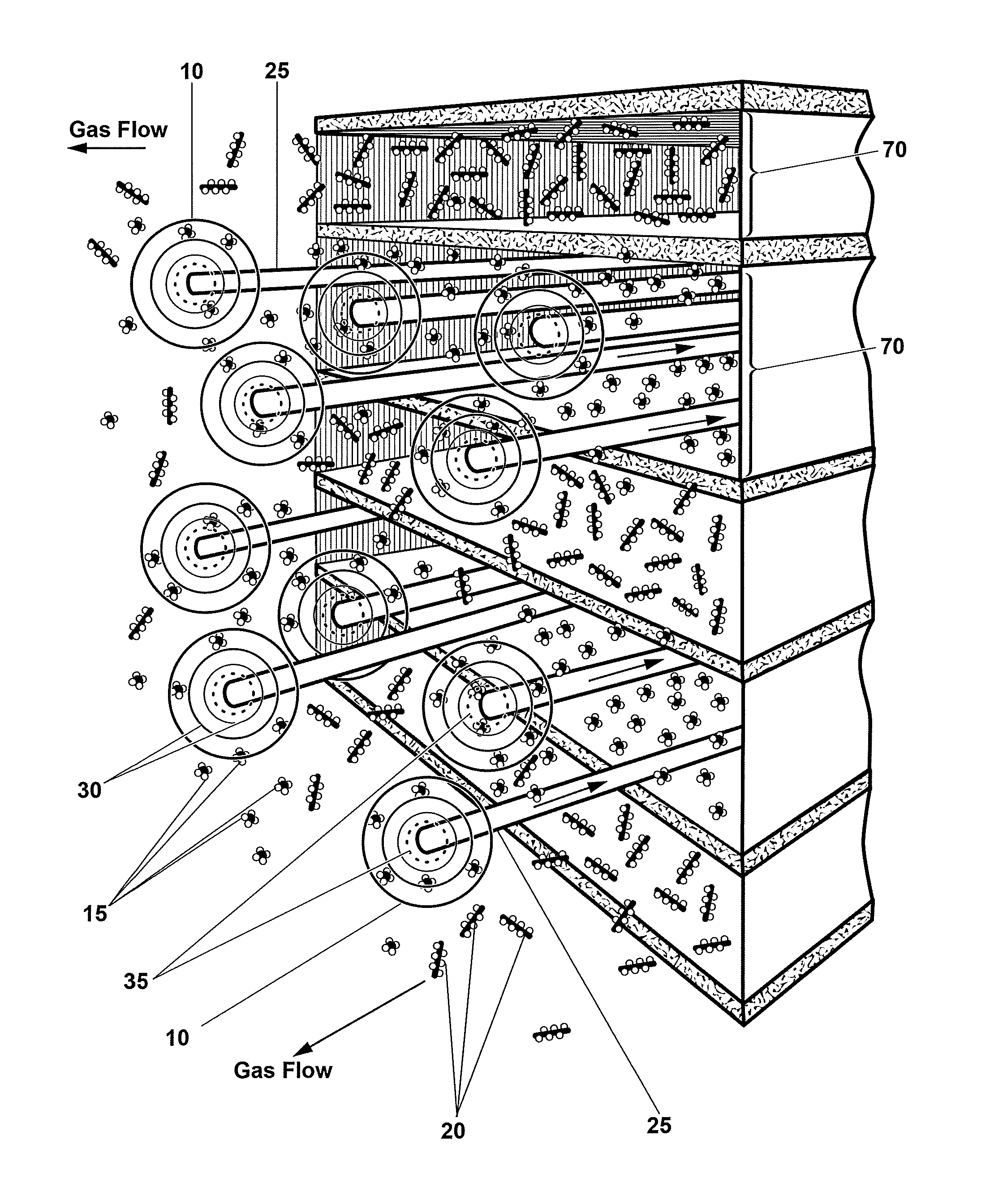
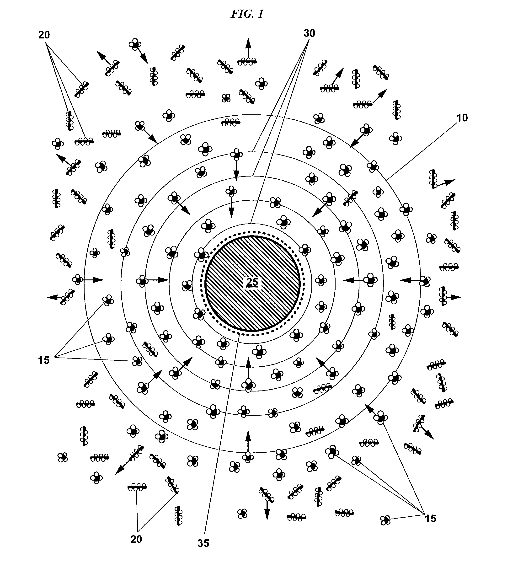
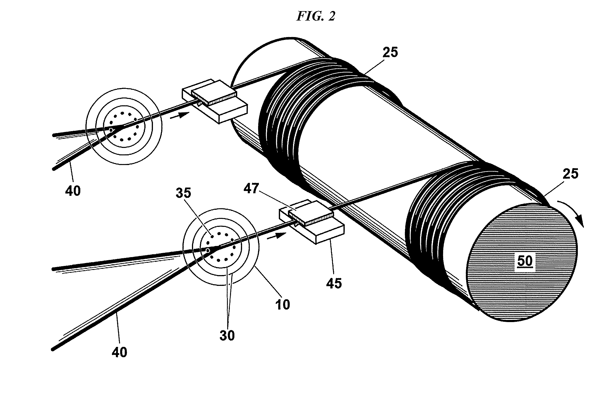
[0075]FIGS. 1 through 40 illustrate various views and embodiments of the present invention, and supporting graphs and data. Various embodiments may have one or more of the components outlined below. Component reference numbers used in the Figures are also provided.[0076]10 thermal diffusion region[0077]15 low molar mass (or LMM) precursor[0078]20 high molar mass (or HMM) precursor[0079]25 fiber[0080]30 concentration gradient[0081]35 reaction zone[0082]40 primary heating means[0083]45 tensioner[0084]47 tension adjustment device[0085]50 spooling device / mandrel[0086]55 coaxial tube[0087]60 low molar mass (or LMM) precursor tube[0088]65 high molar mass (or HMM) precursor tube[0089]70 precursor planar flow sheets[0090]75 gas bubble[0091]80 internal thermal diffusion region[0092]85 external thermal diffusion region[0093]90 fluid (internal in two phase system)[0094]95 vessel seals[0095]100 vessel walls[0096]101 solid source of HMM precursor (e.g. wax)[0097]102 liquid source of HMM precurso...


PUM

PropertyMeasurementUnit
Pressureaaaaaaaaaa
Massaaaaaaaaaa
Concentrationaaaaaaaaaa

Abstract

The disclosed methods and apparatus improve the fabrication of solid fibers and microstructures. In many embodiments, the fabrication is from gaseous, solid, semi-solid, liquid, critical, and supercritical mixtures using one or more low molar mass precursor(s), in combination with one or more high molar mass precursor(s). The methods and systems generally employ the thermal diffusion/Soret effect to concentrate the low molar mass precursor at a reaction zone, where the presence of the high molar mass precursor contributes to this concentration, and may also contribute to the reaction and insulate the reaction zone, thereby achieving higher fiber growth rates and/or reduced energy/heat expenditures together with reduced homogeneous nucleation. In some embodiments, the invention also relates to the permanent or semi-permanent recording and/or reading of information on or within fabricated fibers and microstructures. In some embodiments, the invention also relates to the fabrication of certain functionally-shaped fibers and microstructures. In some embodiments, the invention may also utilize laser beam profiling to enhance fiber and microstructure fabrication.

Description

CROSS-REFERENCE TO RELATED APPLICATIONS[0001]This application claims priority to, and the benefit of, U.S. Application Ser. No. 62 / 038,705 titled “Method and Apparatus of Fabricating Fibers from Disparate Molecular Mass Gaseous, Liquid, Critical and Supercritical Fluid Mixtures,” filed Aug. 18, 2014; U.S. Application Ser. No. 62 / 074,703 titled “Doped Carbon Fibers and Carbon-Alloy Fibers and Method of Fabricating Thereof from Disparate-Molecular Mass Gaseous-, Liquid, and Supercritical Fluid Mixtures,” filed Nov. 4, 2014; and U.S. Application Ser. No. 62 / 074,739 titled “Method and Apparatus for Recording Information on Modulated Fibers and Textiles and Device for Reading Same,” filed Nov. 4, 2014, the entire contents of which are herein incorporated by reference.STATEMENT REGARDING FEDERALLY SPONSORED RESEARCH OR DEVELOPMENT[0002]N / ABACKGROUND OF THE INVENTIONField of the Invention[0003]The present invention is in the technical field of fiber and microstructure fabrication. In some ...

Claims


Application Information

Patent Timeline
IPC IPC(8): C23C16/48C23C16/20C23C16/08D01F8/18C23C16/50C23C16/52
CPCC23C16/483C23C16/50C23C16/486C23C16/20C23C16/08D01F8/18C23C16/52D04H1/4242C04B35/62272D01F9/127C04B35/58C04B35/58007C04B35/58028C04B35/62277C04B35/62286C04B2235/5296C23C16/4418C23C16/26C23C16/481C23C16/45563C23C16/46C23C16/32C23C16/487
Inventor MAXWELL, JAMES L.WEBB, NICHOLASALLEN, JAMES
Owner DYNETICS
Why Eureka
Try Eureka