Drive control device using pwm control of synchronous rectification type

Inactive Publication Date: 2016-12-22
RISO KAGAKU CORP
View PDF0 Cites 1 Cited by
  • Summary
  • Abstract
  • Description
  • Claims
  • Application Information

AI Technical Summary

Benefits of technology

[0011]In the configuration described above, in the stop period lasting for the specified time or longer during the driving of the motor, the controller controls the driver such that the PWM control of the synchronous rectification type is stopped

Problems solved by technology

Accordingly, if the duty ratio of the PWM signal is set to 50% in order to set the motor to the stop state, t

Method used


Image

  • Drive control device using pwm control of synchronous rectification type
  • Drive control device using pwm control of synchronous rectification type
  • Drive control device using pwm control of synchronous rectification type

Examples


Embodiment Construction

[0053]In the following detailed description, for purposes of explanation, numerous specific details are set forth in order to provide a thorough understanding of the disclosed embodiments. It will be apparent, however, that one or more embodiments may be practiced without these specific details. In other instances, well-known structures and devices are schematically shown in order to simplify the drawing.

[0054]Description will be hereinbelow provided for embodiments of the present invention by referring to the drawings. It should be noted that the same or similar parts and components throughout the drawings will be denoted by the same or similar reference signs, and that descriptions for such parts and components will be omitted or simplified. In addition, it should be noted that the drawings are schematic and therefore different from the actual ones.

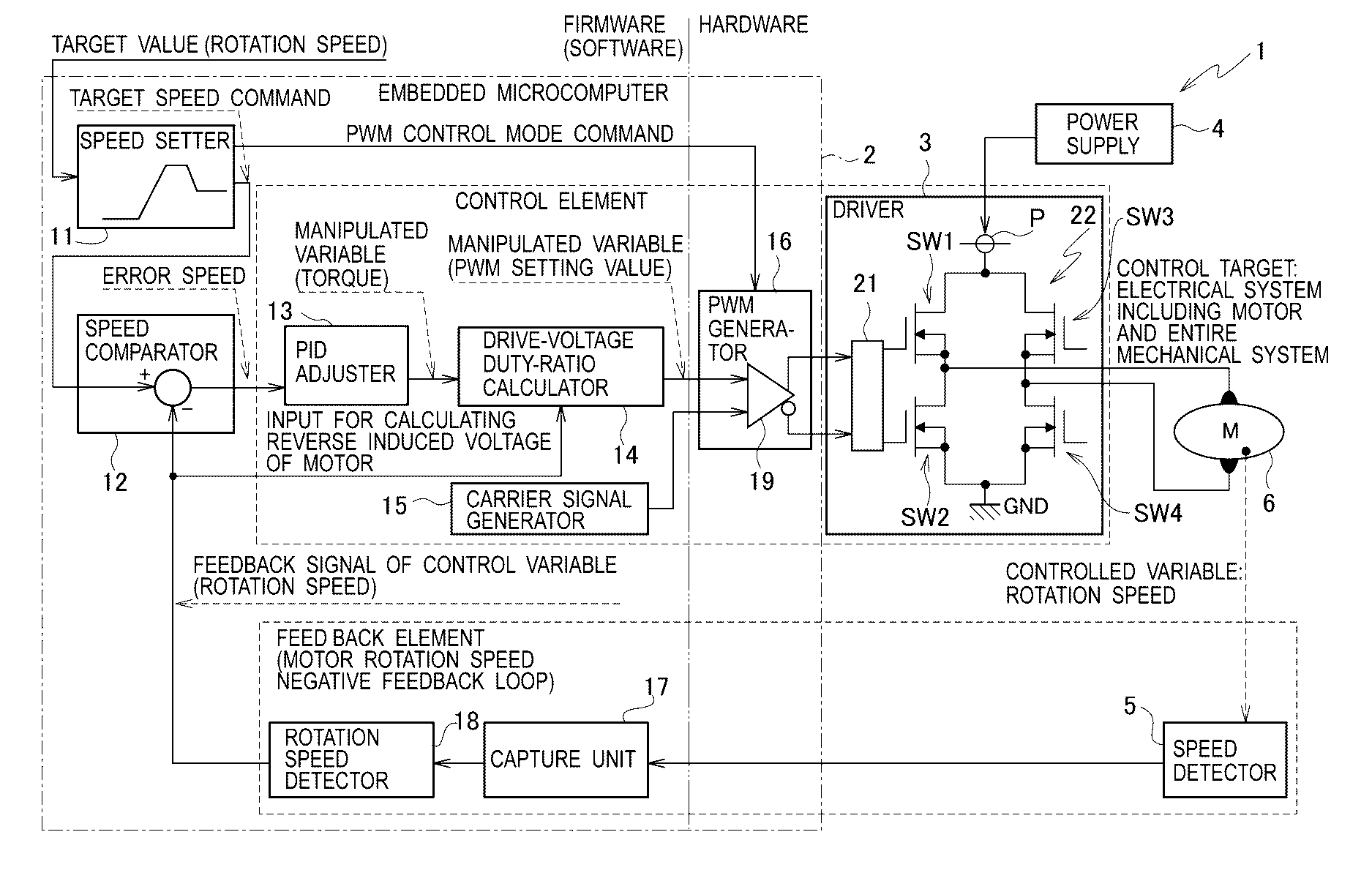
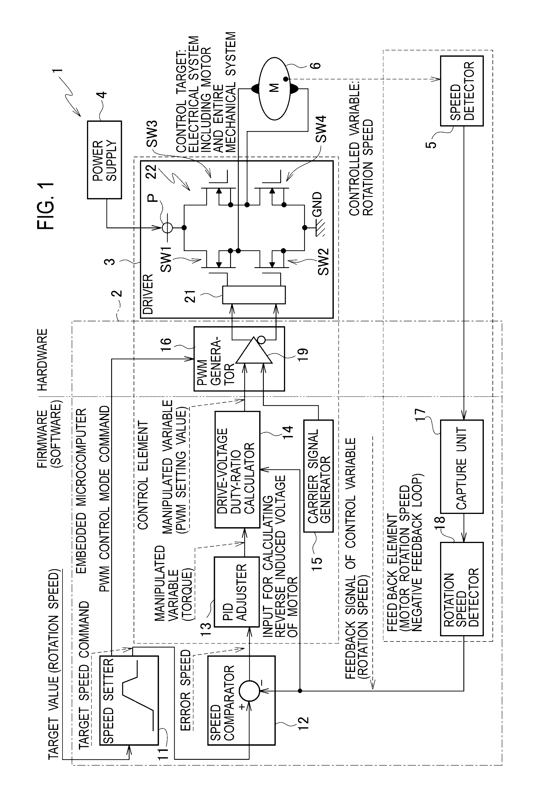
[0055]FIG. 1 is a schematic configuration diagram of a drive control device 1 according to an embodiment of the present invention. As ...


PUM


Abstract

A drive control device includes: a driver including a circuit and configured to drive a motor; and a controller configured to control the driver. The controller is configured to: in a period other than a stop period during driving of the motor, control the driver by a PWM control of a synchronous rectification type, the stop period lasting for a specified time or longer during the driving of the motor; and in the stop period during the driving of the motor, suspend the PWM control of the synchronous rectification type and control the driver such that the motor is set to a short-circuit brake state or a disconnected state.

Description

CROSS REFERENCE TO RELATED APPLICATION[0001]This application is based upon and claims the benefit of priority from the prior Japanese Patent Application No. 2015-123604, filed on Jun. 19, 2015, the entire contents of which are incorporated herein by reference.BACKGROUND[0002]1. Technical Field[0003]The disclosure relates to a drive control device configured to drive a motor.[0004]2. Related Art[0005]Japanese Unexamined Patent Application Publication No. 2014-165982 proposes a drive control device configured to drive a motor by performing pulse width modulation (PWM) control.[0006]A synchronous rectification type is known as one of the PWM control methods. The synchronous rectification type is a method in which a direction of a voltage applied to the motor is switched over in synchronization with switching between an L (low) period and an H (high) period of a PWM signal.SUMMARY[0007]In the PWM control of the synchronous rectification type, the sign (negative or positive) of an averag...

Claims


Application Information

Patent Timeline
IPC IPC(8): H02P27/08H02P3/22
CPCH02P3/22H02P27/08H02P3/12H02P7/29H02P7/04
Inventor SUZUKI, MASAO
Owner RISO KAGAKU CORP
Why Eureka
Try Eureka