
Keyless entry apparatus

a keyless entry and key technology, applied in the direction of anti-theft devices, electrical locking circuits, instruments, etc., can solve the problems of inability to discriminate, door cannot be unlocked, portable devices cannot be started up, etc., to achieve accurate predetermined control of the vehicle, suppress the influence of noise, and reliably perform measurement of the reception intensity of measurement signals

Inactive Publication Date: 2016-12-29
ALPS ALPINE CO LTD
View PDF4 Cites 3 Cited by
  • Summary
  • Abstract
  • Description
  • Claims
  • Application Information

AI Technical Summary

Benefits of technology

The present invention provides a keyless entry system that can reliably measure the distance between a vehicle and a portable device at predetermined intervals even when the user carries an information device. This helps to reduce control errors due to start-up failure of the portable device. The system allows the portable device to transmit a measurement signal at predetermined times and wait for the signal at a predetermined timing, eliminating the need for constant start-up of the device. This reduces the impact of noise from other devices and ensures accurate control of the vehicle. The system also uses a threshold value to prevent unnecessary power consumption in the portable device when background noise is equal to or higher than a predetermined level. Overall, this invention provides a more reliable and accurate way to control a vehicle with a portable device.

Problems solved by technology

Therefore, the start-up signal transmitted from the vehicle-side device may be buried in noise signals other than such a signal and may not be able to be discriminated from these.
Accordingly, the portable device cannot be started up.
Accordingly, there is a problem in that the vehicle-side device erroneously determines that the portable device is at a position away from the vehicle regardless of an actual position of the portable device, a door is locked though a user is near the vehicle, and the door cannot be unlocked though the user is approaching.

Method used


Image

  • Keyless entry apparatus
  • Keyless entry apparatus
  • Keyless entry apparatus

Examples


first embodiment

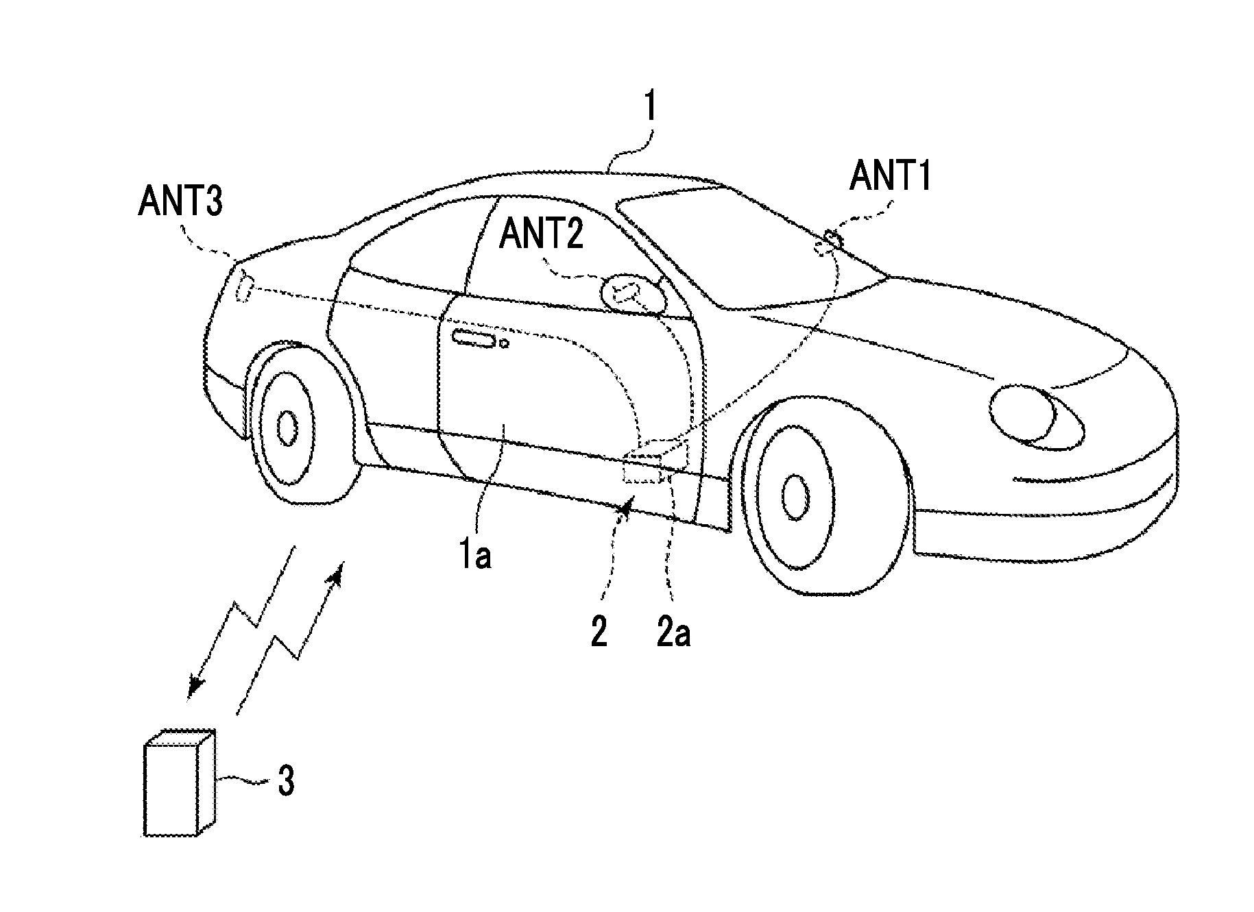
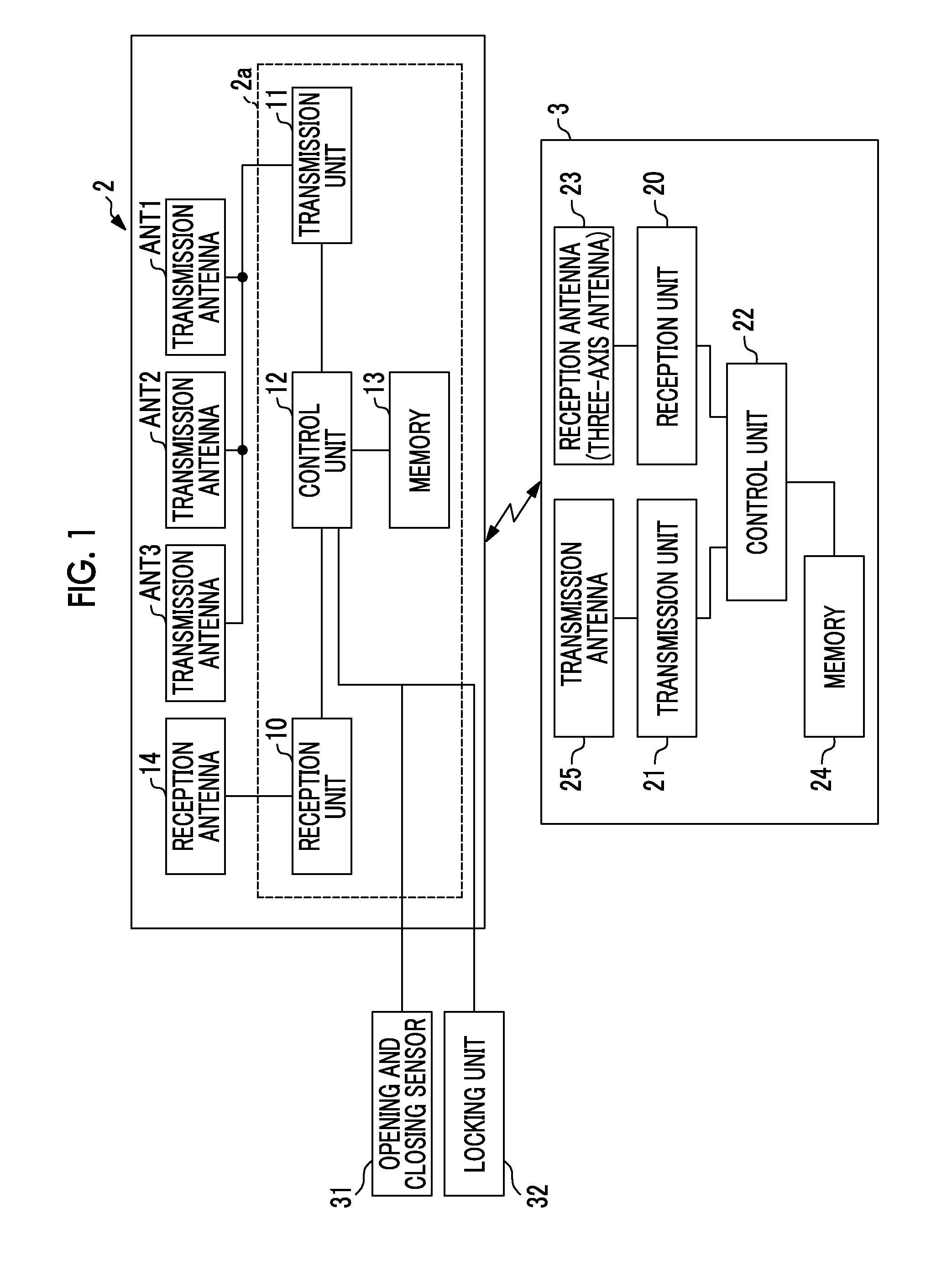
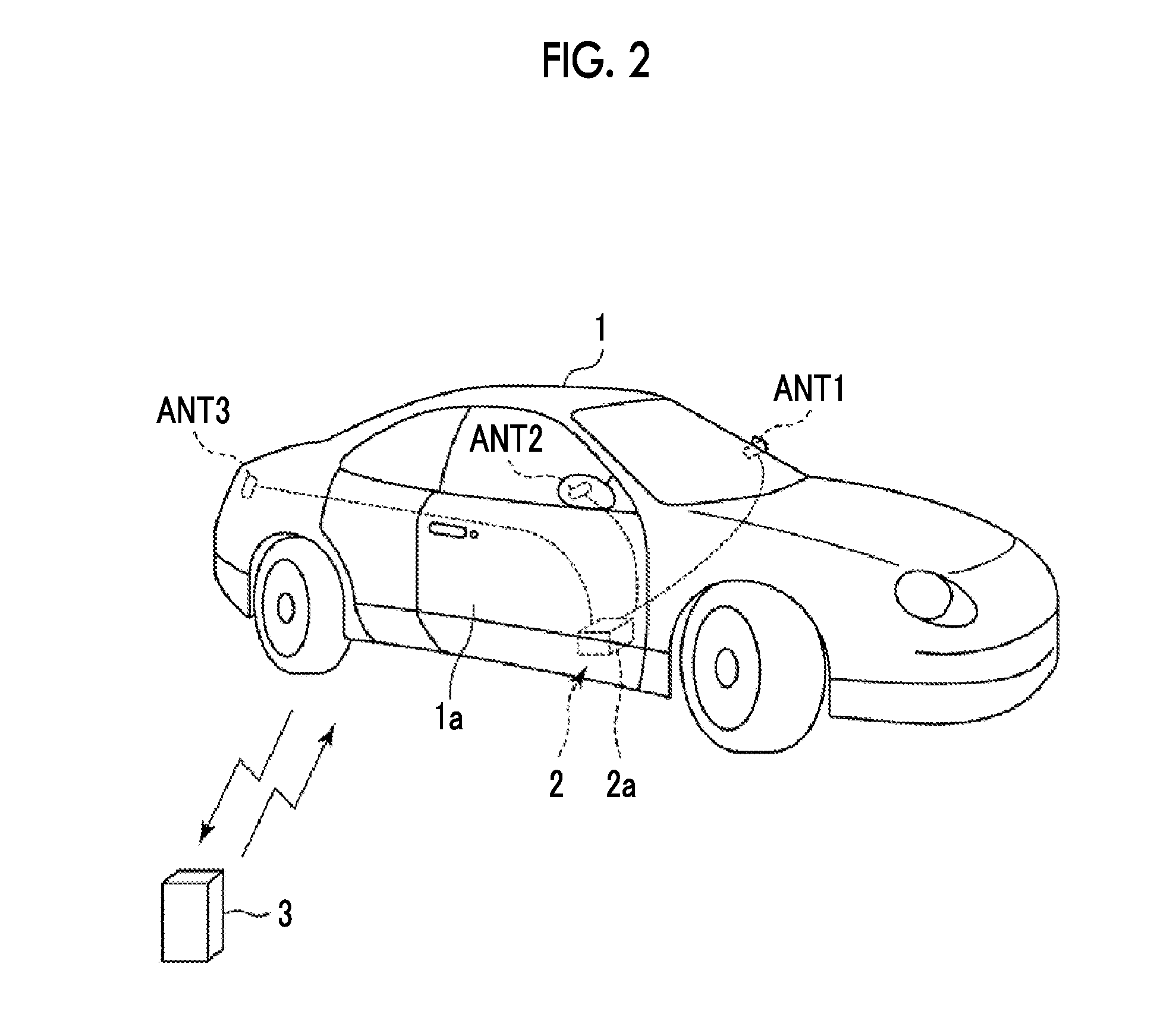
[0026]FIG. 1 is a block diagram illustrating a configuration of a keyless entry apparatus according to a first embodiment, and FIG. 2 is a perspective view illustrating a configuration of a vehicle-side device according to the first embodiment. In the keyless entry apparatus according to the first embodiment, a vehicle-side device 2 is provided on a vehicle 1 side, performs wireless communication with a portable device 3 that can be carried by a user, and performs locking and unlocking of the door 1a and predetermined other control of the vehicle 1.

[0027]The vehicle-side device 2 includes an electronic control unit 2a disposed in the vehicle 1, a plurality of transmission antennas ANT1 to ANT3 as a first transmission antenna, and a reception antenna 14. The electronic control unit 2a includes a vehicle-side reception unit 10 (reception unit), a vehicle-side transmission unit 11 (transmission unit), a vehicle-side control unit 12 (control unit), and a memory 13.

[0028]The vehicle-side...

second embodiment

[0052]A keyless entry apparatus according to a second embodiment of the present invention will be described with reference to FIGS. 4 and 5. In the second embodiment, the same configuration as that in the first embodiment illustrated in FIGS. 1 and 2 is included. In the following description, detailed description of the same configuration, operation, and effects as in the first embodiment will be omitted. FIG. 4 is a timing chart illustrating a timing of transmission and reception of signals in the vehicle-side device and the portable device and a state of the portable device when a signal intensity of noise component data is smaller than a threshold value in the second embodiment. FIG. 5 is a timing chart illustrating a timing of transmission and reception of signals in the vehicle-side device and the portable device, noise generated by an information device, and a state of the portable device when the signal intensity of noise component data is equal to or greater than a threshold...


PUM


Abstract

A vehicle-side device that is provided on the vehicle side and transmits a signal at a first frequency, and a portable device that is able to be carried by a user and transmits a signal at a second frequency are included. The portable device transmits a signal of data based on a reception intensity of a measurement signal transmitted from the vehicle-side device, and the vehicle-side device performs predetermined control on the basis of the data based on the reception intensity of the measurement signal transmitted from the portable device. The vehicle-side device transmits a start-up signal to the portable device, the portable device transmits a request signal or a signaling signal to the vehicle-side device at predetermined time intervals when receiving the start-up signal, and the vehicle-side device transmits the measurement signal to the portable device each time the vehicle-side device receives the request signal or the signaling signal.

Description

CLAIM OF PRIORITY[0001]This application claims benefit of Japanese Patent Application No. 2014-099746 filed on May 13, 2014 and International Application No. PCT / JP2015 / 062404 filed on Apr. 23, 2015, which are hereby incorporated by references.BACKGROUND OF THE INVENTION[0002]1. Field of the Invention[0003]The present invention relates to a keyless entry apparatus that performs predetermined control such as locking and unlocking of doors of a vehicle by performing communication between a vehicle-side device and a portable device.[0004]2. Description of the Related Art[0005]A smart keyless entry apparatus in which wireless communication is performed between a vehicle-side device provided in a vehicle and a portable device carried by a user, and a door of the vehicle is locked or unlocked on the basis of this communication has been proposed (for example, Japanese Unexamined Patent Application Publication No. 2010-181295). In this smart keyless entry apparatus, the vehicle-side device ...

Claims


Application Information

Patent Timeline
IPC IPC(8): B60R25/04E05B81/54B60R25/24E05B81/70
CPCB60R25/04B60R25/24E05B81/54E05B81/70B60R25/245G07C9/00309G07C2009/00769G07C2209/63
Inventor MIYAZAWA, AKIRA
Owner ALPS ALPINE CO LTD
Learn More