Motor drive control device, compressor, air-sending device, and air-conditioning apparatus

a control device and motor technology, applied in the direction of motor/generator/converter stopper, electronic commutator, dynamo-electric converter control, etc., can solve the problems of reduced operation efficiency of motor or inverter circuit, circuit loss, and reduced operation efficiency, and achieve high reliability

Active Publication Date: 2016-12-29
MITSUBISHI ELECTRIC CORP
View PDF4 Cites 19 Cited by
  • Summary
  • Abstract
  • Description
  • Claims
  • Application Information

AI Technical Summary

Benefits of technology

[0020]According to the present invention, even when the boosting circuit is in operation, a ripple current flowing through the smoothing capacitor can be ...

Problems solved by technology

As a result, in the overload operation different from the rated operation, the operation efficiency of the motor or the inverter circuit is decreased.
In the conventional motor drive control device, when the boosting circuit performs a boosting operation, driving the switching element causes a circuit loss.
Thus, in the conventional m...

Method used


Image

  • Motor drive control device, compressor, air-sending device, and air-conditioning apparatus
  • Motor drive control device, compressor, air-sending device, and air-conditioning apparatus
  • Motor drive control device, compressor, air-sending device, and air-conditioning apparatus

Examples


embodiment 1

[0035]A configuration, operation, and advantageous effects of the motor drive control device 1 according to Embodiment 1 of the present invention will be described below in sequence with reference to the drawings.

(Configuration of Motor Drive Control Device 1)

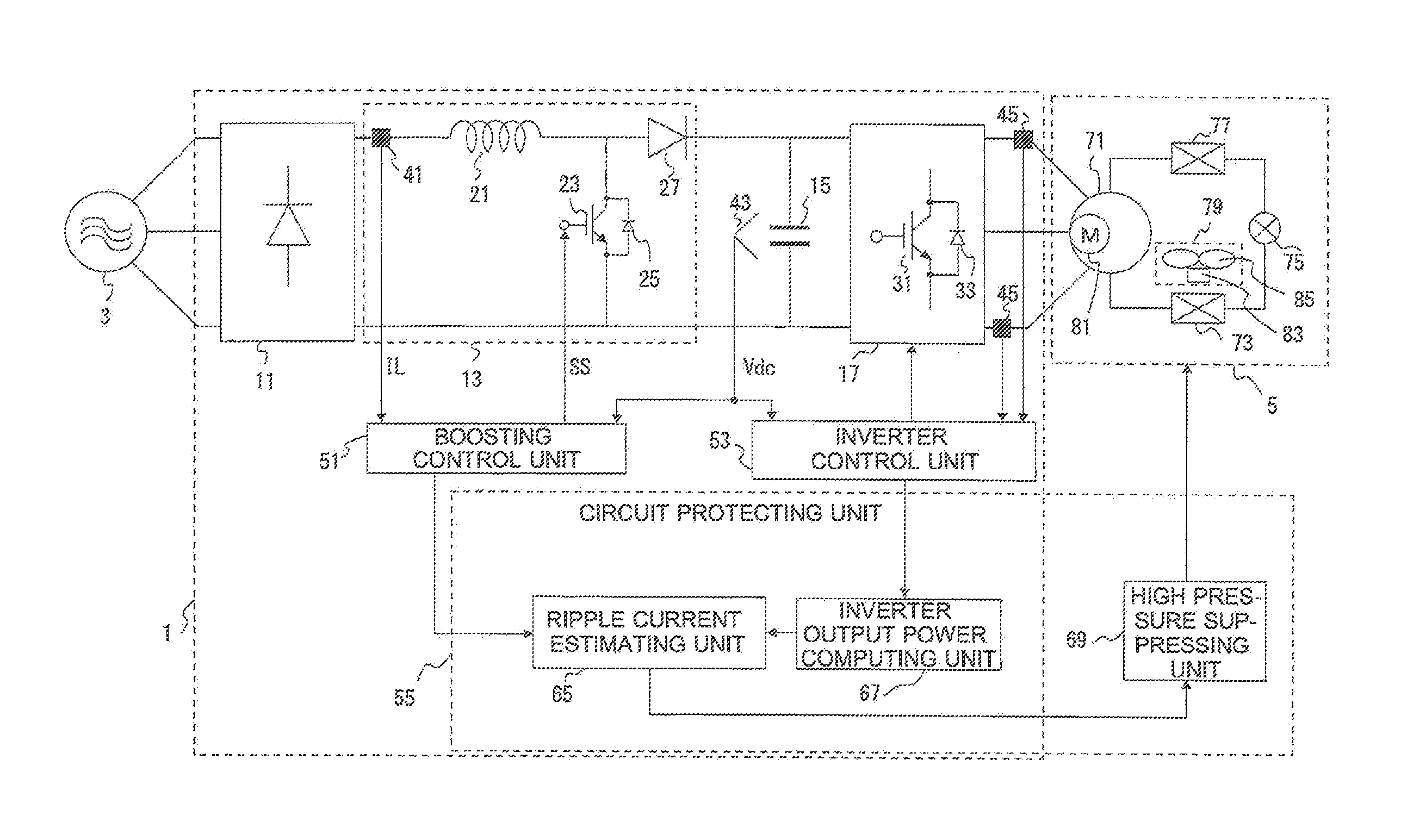
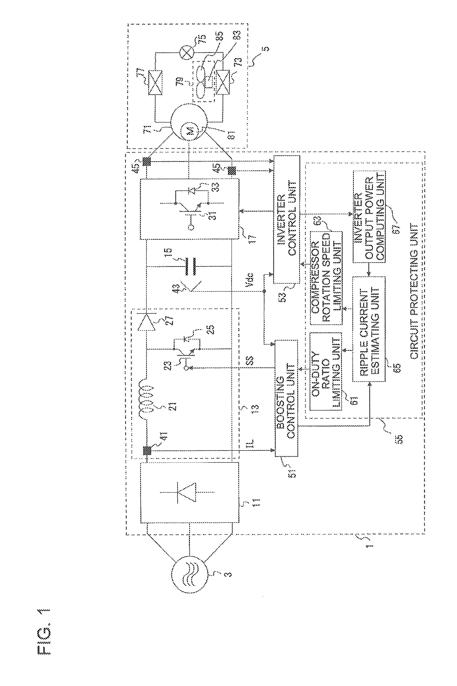
[0036]A configuration of the motor drive control device 1 according to Embodiment 1 of the present invention will be described. FIG. 1 illustrates a general configuration of the motor drive control device 1 according to Embodiment 1 of the present invention, and a general configuration of a refrigerant circuit 5 including the compressor 71 driven by the motor drive control device 1. As illustrated in FIG. 1, the motor drive control device 1 is disposed between a three-phase alternating-current power supply 3 and the refrigerant circuit 5. The motor drive control device 1 converts power supplied from the three-phase alternating-current power supply 3, and supplies the resulting power to the motor 81, such as a load M, of the com...

embodiment 2

Configuration of Motor Drive Control Device 1

[0141]The motor drive control device 1 according to Embodiment 2 will be described with reference to FIGS. 8 and 9. As described in Embodiment 1, as the inverter output power of the inverter circuit 17 increases, a ripple current flowing through the smoothing capacitor 15 increases. In Embodiment 1, the rotation speed of the compressor 71 is limited to reduce the inverter output power of the inverter circuit 17. Embodiment 2 provides a configuration including a high pressure suppressing unit 69 configured to control the pressure conditions of the air-conditioning apparatus.

[0142]FIG. 8 illustrates a general configuration of the motor drive control device 1 according to Embodiment 2 of the present invention, and a general configuration of the refrigerant circuit 5 including the compressor 71 driven by the motor drive control device 1. As illustrated in FIG. 8, the circuit protecting unit 55 includes the ripple current estimating unit 65, t...


PUM


Abstract

A motor drive control device includes a three-phase rectifier; a boosting circuit including a reactor, a switching element, and a backflow preventing element and boosts a direct-current bus voltage supplied from the three-phase rectifier; a smoothing capacitor; an inverter circuit; a boosting control unit; an inverter control unit; and a circuit protecting unit suppresses a ripple current flowing through the smoothing capacitor. In the circuit protecting unit, a correlation of an on-duty ratio of the switching element included in the boosting circuit, the output power of the inverter circuit, and an estimated ripple current are set. On the basis of the on-duty ratio of the switching element, output power of the inverter circuit, and the correlation, the circuit protecting unit determines an estimated ripple current flowing through the smoothing capacitor. When the estimated ripple current exceeds a preset threshold, the circuit protecting unit suppresses the ripple current.

Description

TECHNICAL FIELD[0001]The present invention relates to a motor drive control device, a compressor, an air-sending device, and an air-conditioning apparatus.BACKGROUND ART[0002]Conventional motor drive control devices include one that is configured to generate a direct-current bus voltage for driving an inverter from an alternating-current power supply, such as a commercial power supply. Such a motor drive control device is used, for example, as a drive source for driving a motor of a compressor of an air-conditioning apparatus.[0003]When the motor drive control device is used as a drive source for driving a motor of a compressor of an air-conditioning apparatus, the motor is often designed, for the purpose of improving energy consumption efficiency during rated operation, so that an induced voltage (counter electromotive force) and a power supply voltage are substantially the same at around a rated rotation speed.[0004]For example, in an overload operation where the motor is operated...

Claims


Application Information

Patent Timeline
IPC IPC(8): H02P29/50H02P6/14F25B49/02H02P27/08
CPCH02P29/50H02P27/08H02P6/14F25B49/025F25B2600/0253F25B2600/111F25B2600/112F25B2500/07F25B2700/151F25B49/022H02M1/14H02M7/537H02M1/4225Y02B70/10H02M1/007
Inventor TSUMURA, AKIHIROKUSUBE, SHINSAKUYUASA, KENTA
Owner MITSUBISHI ELECTRIC CORP
Why Eureka
Try Eureka