Transmission brake device

a technology of transmission brake and transmission shaft, which is applied in the direction of mechanical actuated clutches, braking systems, gearing, etc., can solve the problems of increasing drive loss, obstructing the improvement of fuel economy of engines, and high owc costs, so as to reduce sliding resistance

Active Publication Date: 2017-01-12
MAZDA MOTOR CORP
View PDF4 Cites 7 Cited by
  • Summary
  • Abstract
  • Description
  • Claims
  • Application Information

AI Technical Summary

Benefits of technology

[0012]An object of the present invention is to provide a transmission brake device including an engaging piston and a clearance

Problems solved by technology

However, the OWC costs high.
This may obstruct improvement of fuel economy of an engine.
An increase in the sliding resistance b

Method used


Image

  • Transmission brake device
  • Transmission brake device
  • Transmission brake device

Examples


first embodiment

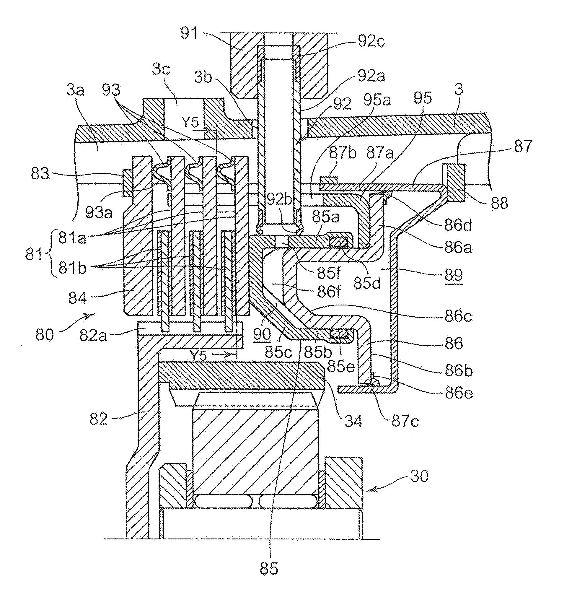
[0056]Next, an operation of the first embodiment is described. At the time of engagement, a hydraulic pressure is supplied from the state illustrated in FIG. 3 and FIG. 4 to the clearance adjustment hydraulic chamber 89 through the adjustment hydraulic oil supply passage 94. By supply of the hydraulic pressure, the clearance adjustment piston 86 is stroked toward the side of the friction plate set 81, and the projecting portion 86f formed at a tip end of the bulging portion 86c of the clearance adjustment piston 86 is abutted against the inner surface of the engaging piston 85. Thereby, the engaging piston 85 is also stroked toward the side of the friction plate set 81.

[0057]Then, at a point of time when the clearance adjustment piston 86 is stroked or moved by the distance x, the tip ends of the teeth 95a of the comb-shaped stopper member 95 formed on the clearance adjustment piston 86 are abutted against the front surface of the retaining plate 84, and strokes of the pistons 85 an...

third embodiment

[0072]In the brake device 380 teeth 95a of a stopper member 95 extend through a substantially rectangular through-hole 381b formed on the outer peripheral side of the fixed-side friction plates 81a. Further, the teeth 95a of the stopper member 95 extend on the inner peripheral side of biasing members 93 in the same manner as in the brake device 280.

[0073]Also, in this embodiment, the stopper member 95 is abutted against a retaining plate 84 when a clearance adjustment piston 86 is moved toward the side of a friction plate set 81 to restrict movement of the clearance adjustment piston 86 at a position where a predetermined clutch clearance is formed. According to this configuration, it is possible to securely restrict movement of the clearance adjustment piston with a relatively simplified configuration.

[0074]Further, in the brake device 80 according to the first embodiment, a portion of the bulging portion 85c of the engaging piston 85 in which the bulging portion 86c of the cleara...

fourth embodiment

[0075]In the brake device 480 seal members 86g and 86h are mounted on groove portions for seal members, which are respectively formed in the outer peripheral wall and in the inner peripheral wall of a bulging portion 86c of a clearance adjustment piston 86, and an outer periphery and an inner periphery of a bulging portion 85c of an engaging piston 85 in which the bulging portion 86c of the clearance adjustment piston 86 is received are respectively sealed by the seal members 86g and 86h. Thus, an engaging hydraulic chamber 90 is oil-tightly formed by the engaging piston 85 and the clearance adjustment piston 86.

[0076]Also, in this embodiment, the engaging hydraulic chamber 90 is formed by the bulging portion 85c of the engaging piston 85 bulging toward the side of a friction plate set 81, and the bulging portion 86c of the clearance adjustment piston 86 bulging toward the side of the friction plate set 81 and received in the bulging portion 85c. According to this configuration, it...


PUM


Abstract

A transmission brake device includes: a friction plate set configured such that a plurality of rotation-side friction plates; an engaging piston disposed on an axial side of the friction plate set; a clearance adjustment piston disposed on a side of the engaging piston opposite to the friction plate set,; a clearance adjustment hydraulic chamber configured to move the clearance adjustment piston; and an engaging hydraulic chamber configured to move the engaging piston; a biasing member disposed between each adjacent pair of the fixed-side friction plates, the biasing member being configured to bias each adjacent pair of the fixed-side friction plates in directions away from each other. The biasing member distributes the clutch clearance in a gap between each adjacent pair of the fixed-side friction plates when a hydraulic pressure is supplied only to the clearance adjustment hydraulic chamber.

Description

TECHNICAL FIELD[0001]The present invention relates to a transmission brake device to be mounted in a vehicle, and belongs to the technical field of a vehicular transmission.BACKGROUND ART[0002]A transmission to be mounted in a vehicle such as an automatic transmission is configured such that gearshift is automatically performed by selective engagement of a power transmission path constituted by a planetary gear mechanism and the like with a plurality of hydraulic friction engagement elements. Each gear position is basically formed by engagement of two friction engagement elements. Conventionally, regarding a first gear position in the D-range, it is a usual practice to form the gear position by one friction engagement element and an OWC (one-way clutch) for the purpose of a smooth gearshift operation and the like.[0003]However, the OWC costs high. Further, a rotational resistance may be generated in a gear position other than the first gear position in the D-range. This may obstruct...

Claims


Application Information

Patent Timeline
IPC IPC(8): F16D65/18F16D55/00F16D25/0635B60T1/06F16H63/30F16D13/46
CPCF16D65/186F16H63/3026F16D13/46F16D25/0635B60T1/062F16D2121/04F16H3/66F16H2200/0052F16H2200/201F16H2200/2043F16D2055/0058F16D55/00F16H57/10F16D13/69F16D25/0638F16D25/126
Inventor IWASAKI, TATSUHIKOKAMADA, SHINYAOGAUCHI, YASUHIRO
Owner MAZDA MOTOR CORP
Why Eureka
Try Eureka