Combined heating and cooling systems

a technology of heating and cooling system and combined heat, which is applied in the direction of heat storage plant, lighting and heating apparatus, heating types, etc. it can solve the problems of inability to control the system, insufficient heating for re-use, and relatively inefficient system, so as to increase the “coefficient of performance” and increase the mass flow of working fluid.

Inactive Publication Date: 2017-01-12
ARRIBA COOLTECH
View PDF6 Cites 3 Cited by
  • Summary
  • Abstract
  • Description
  • Claims
  • Application Information

AI Technical Summary

Benefits of technology

[0006]Embodiments of the above described system are adapted for control to facilitate efficient operation of the system. In particular by providing a controllable thermal store it is easier both to operate the system in an efficient regime when simultaneously heating and cooling and also to achieve stable control of the combined heating and cooling system.
[0008]Use of a stratified thermal storage tank is advantageous as this separates relatively warmer and cooler portions of the heating circuit fluid. This in turn facilitates achieving a low temperature for the input to the gas cooler, this low temperature in the heating circuit facilitating efficient operation of the working fluid circuit. Thus, paradoxically, employing stratified thermal storage not only facilitates obtaining a higher temperature for the portion of the heating circuit used for heating, it also facilities achieving a lower temperature in a different portion of the heating circuit which facilitates efficient operation of the overall system.
[0009]Further, and importantly, use of a stratified thermal storage tank allows the thermal storage tank to be used as a gauge in which the degree of stored thermal energy can be determined from a set of temperature sensors at different levels within the tank. This in turn facilitates control of the system based upon stored energy rather than on temperature per se. In the case of a tank comprising a set of vessels / chambers the stored thermal energy gauge may be provided by a count of the number of vessels / chambers containing hot (warmer) as opposed to cold (cooler) fluid. It is not, however, essential to employ stratified thermal storage as in principle the advantages of such an approach may be achieved in other ways, for example by means of multiple smaller thermal storage tanks.
[0010]In some preferred embodiments the system also includes a thermal dump system to enable heat to be dumped from said heating circuit, again to facilitate efficient overall system control, counter-intuitively dumping thermal energy facilitating an overall energy saving. In embodiments the heating circuit is configured, for example using valves, to direct or switch flow in the circuit between the thermal storage tank and the thermal dump, for example when the thermal store does not need to be replenished.
[0019]Again counter-intuitively, the overall system efficiency can at times be increased by dumping coolth from the cooling side of the system, so as effectively to heat the input to the evaporator (from the cooling circuit) and increase the efficiency of the working fluid circuit. In embodiments the coolth may be dumped by controlling the rate at which a heat exchanger operates (in embodiments, to exchange heat with an ambient, generally external environment); and / or by selecting a series or parallel mode of operation for the cooling circuit. In embodiments the method further comprises selecting a series mode of operation when ‘free’ cooling is available, that is when an ambient environment of the coolth dumping device is less than a target desired temperature for the coolant in the coolth output of the cooling circuit.
[0023]In preferred embodiments a further control system, preferably operating with a shorter cycle time, operates to control the cooling side circuit to control the temperature of the coolant flowing into the evaporator, again preferably by controlling at least dumping of coolth from the cooling side circuit. In embodiments the second control system may operate to control the coolant temperature up towards a target temperature. In broad terms this is advantageous because this raises the pressure of the working fluid (carbon dioxide) in the evaporator, which in turn increases the mass flow of working fluid through the evaporator and compressor, without causing a proportionate rise in the shaft power of the compressor. This helps to raise the “Coefficient of Performance” (COP) of the refrigeration cycle.

Problems solved by technology

Using carbon dioxide as a working fluid in integrated heating and cooling systems that operate on the basis of a vapour-compression cycle has particular environmental benefits, but also poses some special problems.
Generally it has been considered that the jettisoned energy is insufficiently warm for it to be worth re-using in its entirety
However this system is not controllable and is relatively inefficient.

Method used


Image

  • Combined heating and cooling systems
  • Combined heating and cooling systems
  • Combined heating and cooling systems

Examples


example a

Series-Mode Circuit

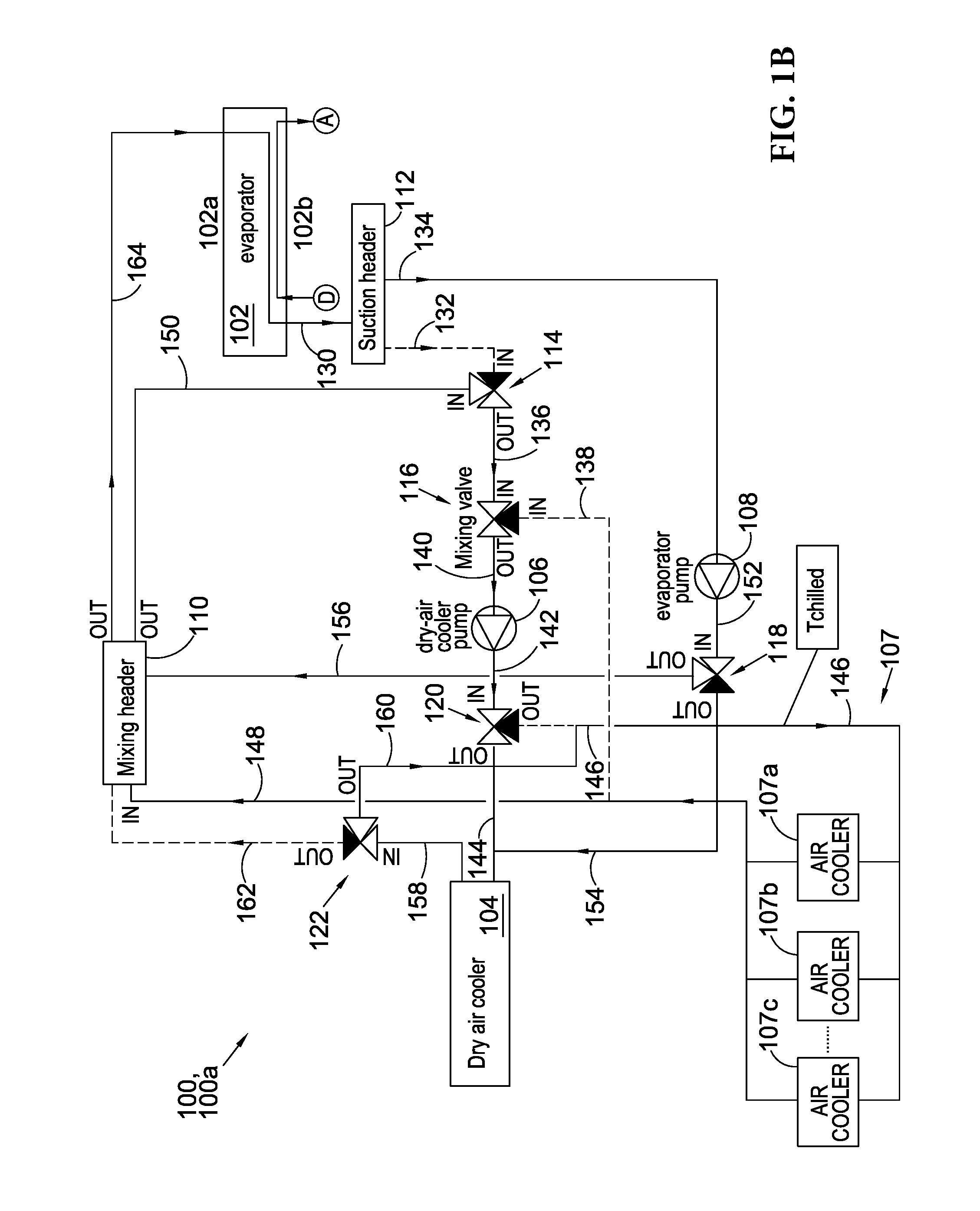
[0117]Referring to FIGS. 8A-8B, which corresponds to FIG. 1B, this example illustrates the effect of using an air blast heat exchanger 104 for cooling during colder weather. FIG. 8A shows temperatures in the system at t=0 minutes and FIG. 8B at t=2 minutes. FIG. 8C corresponds to a version of FIG. 7 and illustrates the main features of a lookup table for control of the (fan of) cooler 104. FIG. 8A corresponds to point a1 in FIG. 8C and FIG. 8B to point a2.

[0118]The target coolant temperature (in the mixing header) is, in this example, 21° C., a temperature suitable, for example, for an industrial process. The ambient temperature is significantly lower than this and if the temperature of the mixing header becomes excessive this can quickly be brought under control by the control of the cooler fan(s), even if the compressor is not providing much cooling effect. As previously discussed, in embodiments the scan rate of the GAM control procedure may be 90 seconds as co...

example b

Parallel-Mode Circuit

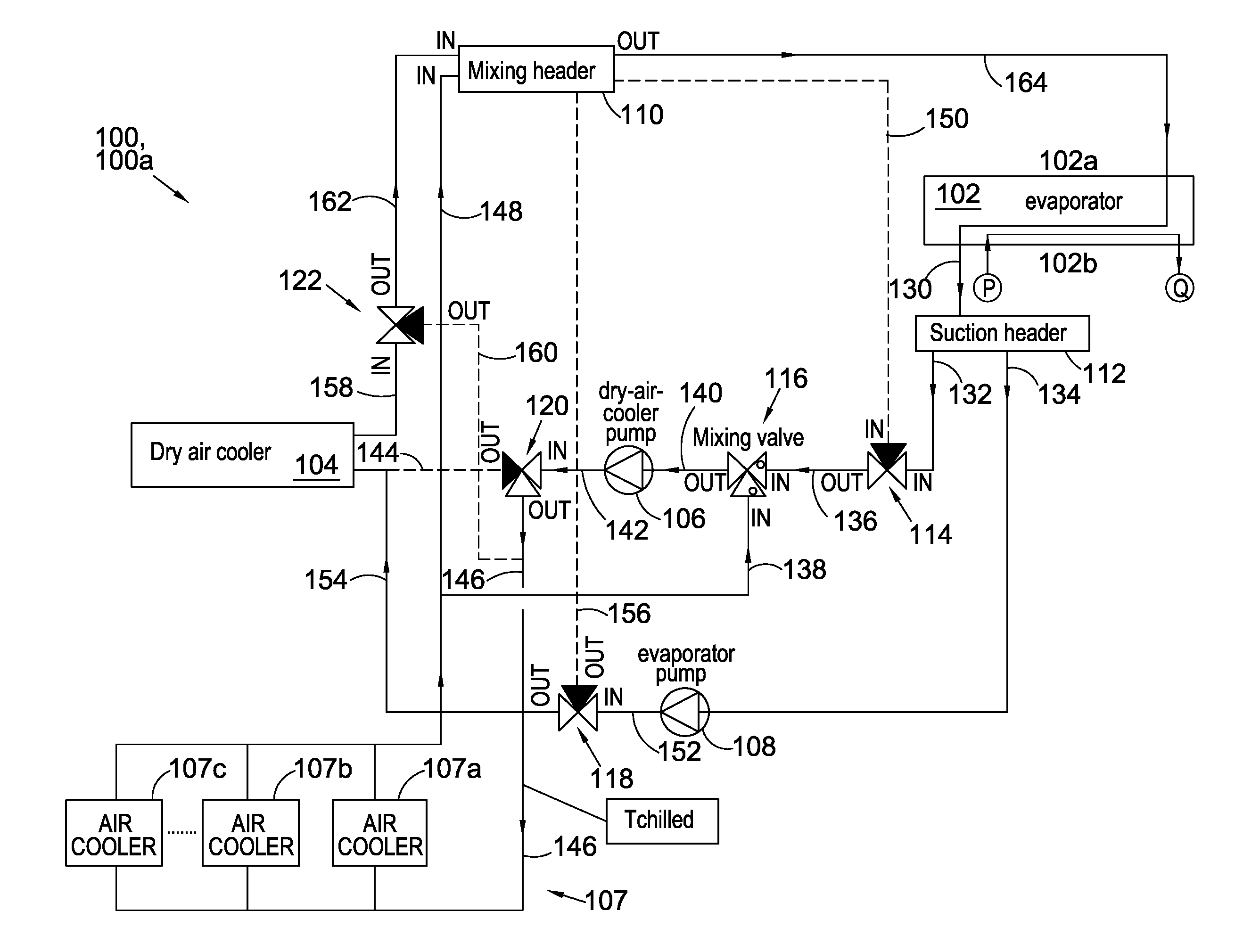
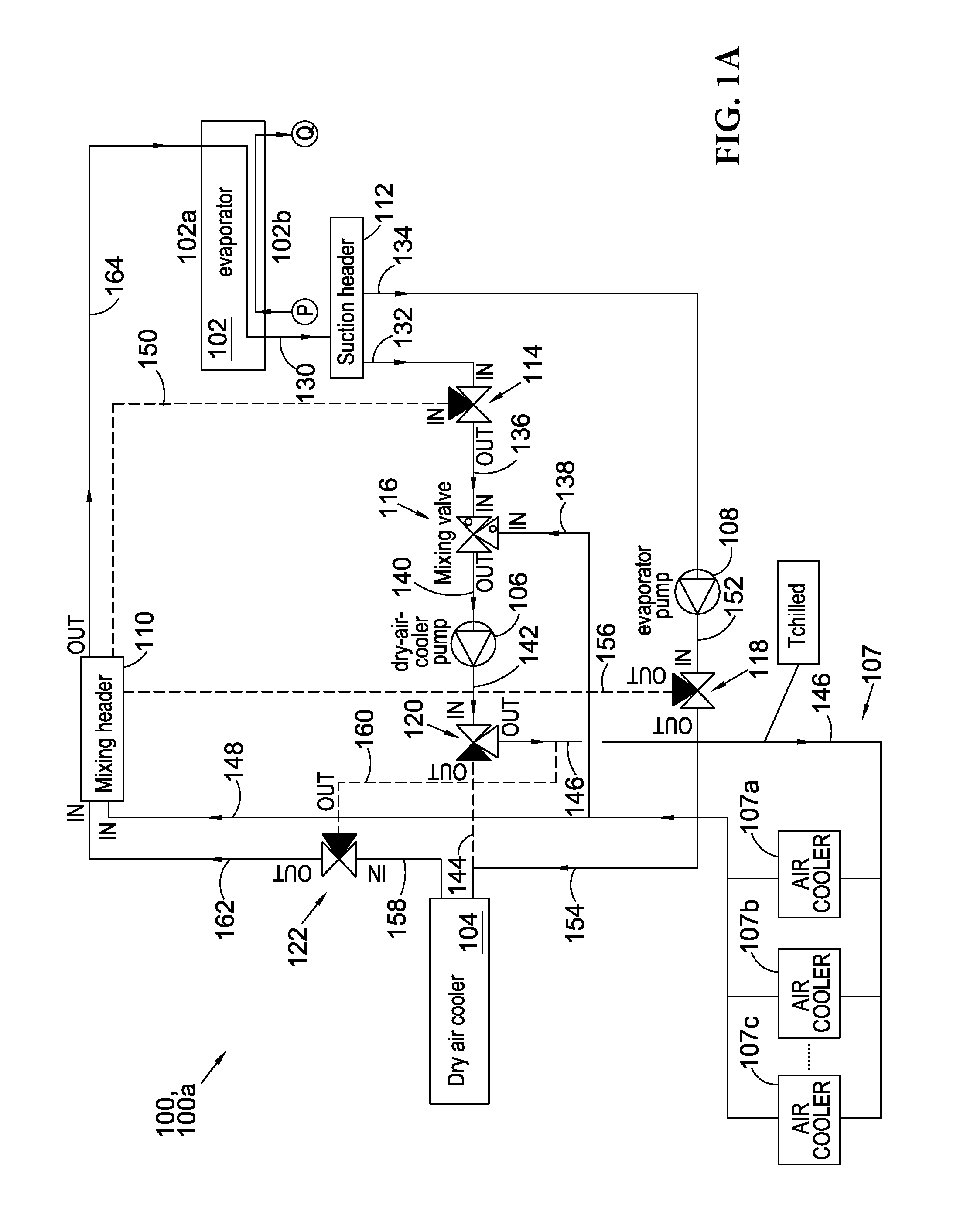
[0119]Referring to FIGS. 9A-9D, which corresponds to FIG. 1A, this example illustrates operation of the system with the cooling side in a parallel mode of operation. Thus FIGS. 9A to 9D show temperatures in the system at, respectively t=0, 6, 12, 18 minutes, and FIG. 9E illustrates the main features of a lookup table for control of the (fan of) cooler 104. In FIG. 9A the recirculation port 138 of mixing valve 116 is closed; in FIG. 9B it is partially open; in FIG. 9C it is wide open; and in FIG. 9D it is partially open once again. The SEL and SCG “gauges” are also illustrated as insets. The target coolant temperature (in the mixing header) is, in this example, 15° C., and the target suction header temperature is 10.0° C. In broad terms, the air blast heat exchanger fan(s) and valves are operated in such a way as to influence the temperature of the mixer header 110. The SCG uses the temperature of the suction header 112 as a means of determining how much or how l...


PUM


Abstract

We describe a combined heating and cooling system, the system comprising: a working fluid circuit comprising a compressor, a gas cooler and an evaporator; a heating circuit, thermally coupled to said working fluid circuit via said gas cooler; and a cooling circuit, thermally coupled to said working fluid circuit via said evaporator; wherein said heating circuit further comprises a thermal storage tank, in particular a stratified thermal storage tank, controllably coupled to said heating circuit to controllably store heat for said heating circuit.

Description

FIELD OF THE INVENTION[0001]This invention relates combined heating and cooling systems, in particular using carbon-dioxide as a working fluid, and to control schemes for such systems.BACKGROUND TO THE INVENTION[0002]Using carbon dioxide as a working fluid in integrated heating and cooling systems that operate on the basis of a vapour-compression cycle has particular environmental benefits, but also poses some special problems. In the vast majority of vapour-compression cooling systems the energy contained within the discharge gas of a refrigeration compressor is jettisoned as if it were a waste product. Generally it has been considered that the jettisoned energy is insufficiently warm for it to be worth re-using in its entirety[0003]A carbon-dioxide-based cooling and heating apparatus can be found in US2008 / 0245505. This describes an apparatus and method with two refrigerating cycle circuits and a sublimation heat exchanger. A heat pump using carbon-dioxide as a refrigerant and nat...

Claims


Application Information

Patent Timeline
Patent Type & Authority Applications(United States)
IPC IPC(8): F28D20/00F28F27/02F25B49/02F25B9/00F25B30/02
CPCF28D20/0039F25B9/008F25B30/02F25B49/02F25B49/022F25B2400/22F25B2700/2111F25B2600/2507F25B2400/01F25B2400/24F28F27/02F25B25/005F25B27/005F25B29/003F25B2309/061F25B2339/047Y02E60/14F24D3/005F24D11/003F24D12/02F24F5/0007F24F2221/18F28D20/0034
Inventor CONNOLLY, STEVE
Owner ARRIBA COOLTECH
Why Eureka
Try Eureka