Method and apparatus for determining a value of a variable parameter

a variable parameter and value technology, applied in the direction of electric control, ignition automatic control, electronic commutators, etc., can solve the problems of time-consuming, cost- and cost-related, and the inability to adjust and/or change the value of variable parameters, so as to reduce the amount of memory space

Active Publication Date: 2017-01-19
NXP USA INC
View PDF6 Cites 3 Cited by
  • Summary
  • Abstract
  • Description
  • Claims
  • Application Information

AI Technical Summary

Benefits of technology

[0005]According to an aspect of the present invention, a control methodology and apparatus for an engine suitable for use in capacitor discharge ignition systems for internal combustion engines or brushless DC motors is provided, which make use of a simple logic block to determine for instance an ignition timing advance angle or duty cycle signal based on actual engine speed versus engine control parameter data stored in a table, which is a read-only memory, preferably configurable. To minimise memory space, a small number of values of engine control parameter versus engine speed are stored in the table and the logic block determines the required engine control signal for a measured value of engine speed by an interpolation process, preferably linear interpolation.

Problems solved by technology

These known systems which require inter alia a battery, a CPU and re-writable memory have the disadvantages of cost, size and complexity.
This makes such systems especially unattractive for use in low-cost equipment such as tools or motorcycles.
Although, such mechanical ignition timing systems are still widely used they are subjected to several drawbacks.
Any adjustments and / or changes required thereof are time- and cost-consuming.

Method used


Image

  • Method and apparatus for determining a value of a variable parameter
  • Method and apparatus for determining a value of a variable parameter
  • Method and apparatus for determining a value of a variable parameter

Examples


Embodiment Construction

[0013]Because the illustrated embodiments of the present invention may for the most part, be implemented using electronic components and circuits known to those skilled in the art, details will not be explained in any greater extent than that considered necessary as illustrated above, for the understanding and appreciation of the underlying concepts of the present invention and in order not to obfuscate or distract from the teachings of the present invention.

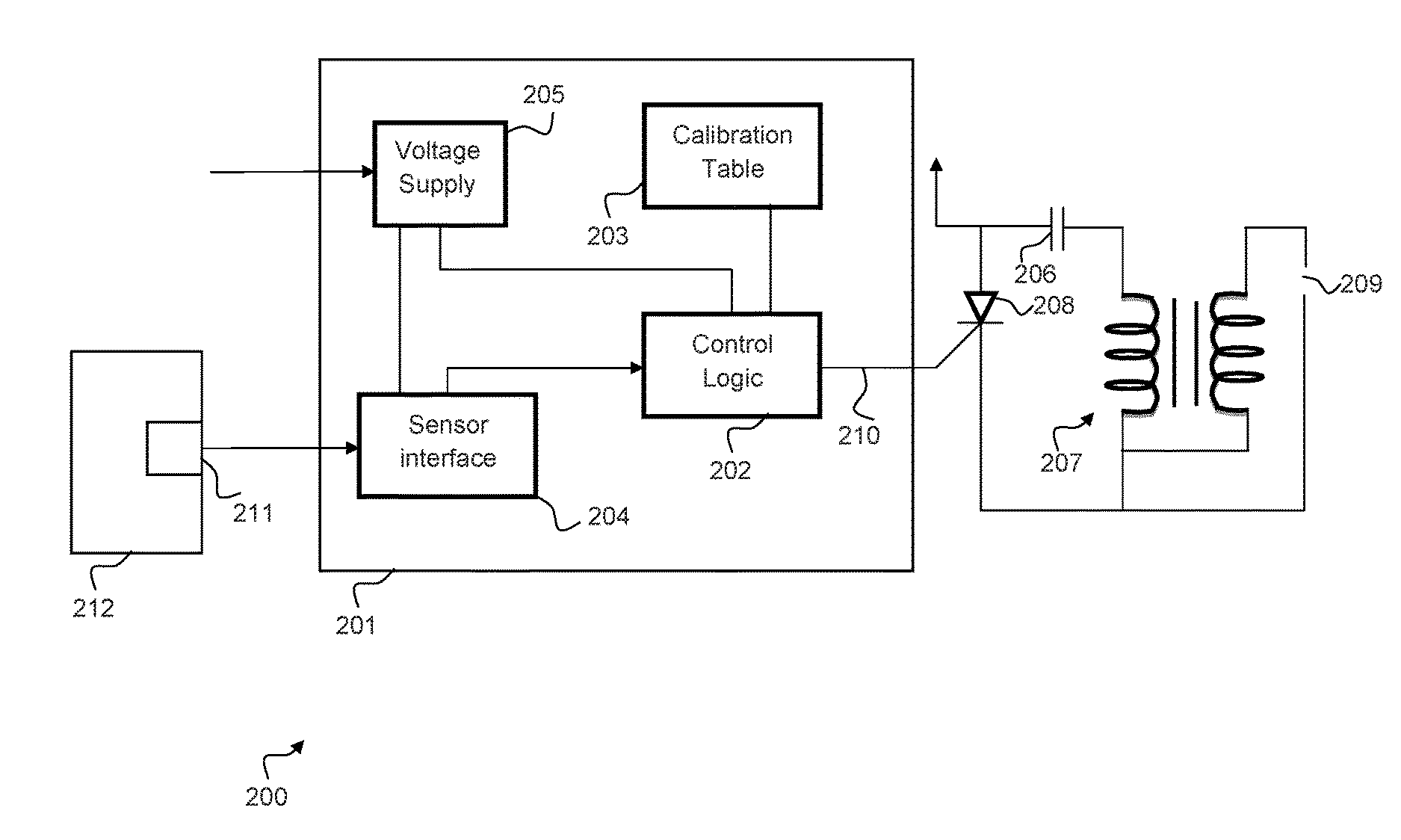
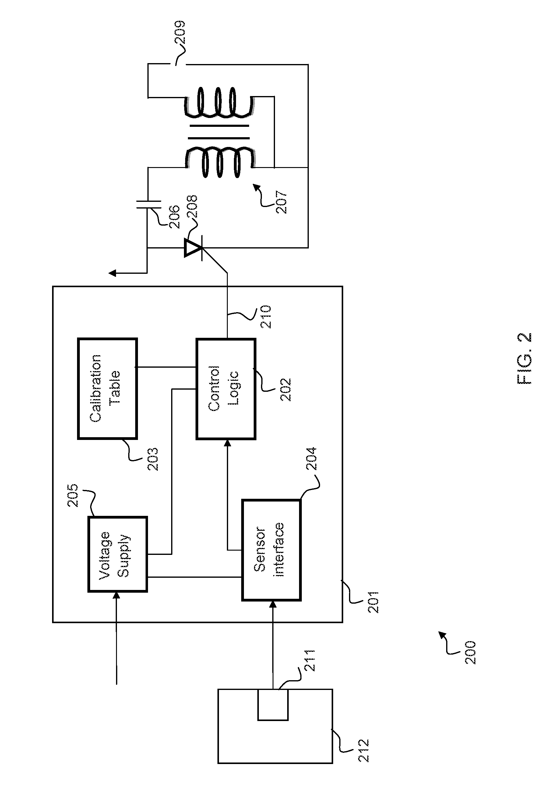
[0014]With reference to FIG. 2, a system 200 for controlling ignition timing in an internal combustion engine of a machine such as a lawn mower may comprise control apparatus 201 which includes a control logic module 202 operably coupled to a calibration table 203. The control logic module 202 is a finite-state machine implemented on the basis of a fixed or fixedly coded logic. The control apparatus may be arranged to determine a value of an ignition timing of an internal combustion engine as a function of a variable parameter r...


PUM


Abstract

A control methodology and apparatus for an engine suitable for use in capacitor discharge ignition systems for internal combustion engines or brushless DC motors is provided, which make use of a simple logic block to determine for instance an ignition timing advance angle or duty cycle signal based on actual engine speed versus engine control parameter data stored in a table, which is a read-only memory, preferably configurable. To minimise memory space, a small number of values of engine control parameter versus engine speed are stored in the table and the logic block determines the required engine control signal for a measured value of engine speed by an interpolation process, preferably linear interpolation.

Description

FIELD OF THE INVENTION[0001]This invention relates to a method and apparatus for determining ignition timing control in an internal combustion engine in particular an ignition timing advance angle. The invention is particularly, though not exclusively, applicable to the control of ignition timing in capacitor discharge ignition systems used on engines for motorcycles and tools such as lawn mowers, vegetation blowers and generators, for example.BACKGROUND OF THE INVENTION[0002]The most prevalent method of controlling spark-ignited IC engines in practice is to use one or more sensors for interpreting engine operating conditions, and choose ignition timing based on such interpreted engine operating conditions using a pre-calibrated map stored in an electronic control unit that controls the ignition timing. The map stored in memory of the electronic control unit is typically constructed using a set of calibration experiments on a set of sample engines that are representative of engines ...

Claims


Application Information

Patent Timeline
Patent Type & Authority Applications(United States)
IPC IPC(8): F02P5/15G01P3/36H02P6/16G01P3/44F02P3/06H02P27/08
CPCF02P5/1514F02P3/06G01P3/36H02P6/16G01P3/44H02P27/08F02D41/2416F02P5/145F02D2400/06F02P9/005Y02T10/40
Inventor GARRARD, MICHAEL ROBERTEDWARDS, WILLIAM E.HALL, JOHN MATTHEW
Owner NXP USA INC
Why Eureka
Try Eureka