Nano-Structured Lens for Collimating Light from Surface Emitters

a surface emitter and lens technology, applied in the field of optics, can solve the problems of large lenses are also expensive to manufacture, and achieve the effects of reducing power consumption, heat generation, cost and size, and reducing the compactness benefits of leds

Active Publication Date: 2017-01-19
DICON FIBEROPTICS
View PDF0 Cites 15 Cited by
  • Summary
  • Abstract
  • Description
  • Claims
  • Application Information

AI Technical Summary

Benefits of technology

[0004]Utilizing the light power contained in the “near-field” can dramatically increase efficiency, which has synergistic benefits such as being able to reduce power usage, heat generation, cost, and size. LEDs are an attractively compact, inexpensive, and reliable light source, but as with light bulbs, their applications typically require the use of collimating and other optical light shaping elements. The light distribution from a surface emitter, such as an LED, follows a Lambertian profile in which the power over a small solid angle is proportional to cosine of the angle between the solid angle and the surface normal. Using bulky geometric lenses that are genera...

Problems solved by technology

Using bulky geometric lenses that are generally several times the size of the source, reduces the compactness benefits of LEDs....

Method used


Image

  • Nano-Structured Lens for Collimating Light from Surface Emitters
  • Nano-Structured Lens for Collimating Light from Surface Emitters
  • Nano-Structured Lens for Collimating Light from Surface Emitters

Examples


Embodiment Construction

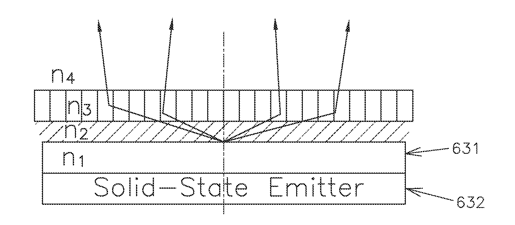
[0020]The present invention utilizes one or more patterned nano-structures which act as a compact lens to efficiently collimate the otherwise spread emission from a light emitting surface, by coherently scattering high-angle light that would be typically wasted with geometric lenses, in the forward direction. Referred to hence forth as a “nano-structured lens”, the present invention's primary functional advantages over geometric lenses are that it is more able to collimate high-angle light and can be placed close to the light emitting surface, to couple energy from the near-field. The nano-structured patterns form a roughly one-dimensional or two-dimensional lattice of index contrast and can be simplistically viewed as an array of holes or higher index pillars in a preferably transparent, low loss medium that is several wavelengths thick. The resulting light pattern in the far-field is the collective interference pattern created by a large number of scattering centers arranged in a ...


PUM


Abstract

A light source for providing light comprises a light emitting layer and a lens comprising a periodic structure therein that is periodic along at least one direction in a plane. The structure includes or is formed from at least two optically transparent materials of different optical indices. The lens is separated from the light emitting layer, and the radiation propagating from the light emitting layer within an angle to a line normal to the plane will be transmitted by the lens to a far field in an index-guided mode. The separation between the light emitting layer and the lens is such that near field radiation propagating from the light emitting layer towards the lens not within said angle to the line will be scattered and redirected by the first lens to the far field to thereby collimate the radiation propagating from the light emitting layer to the far field.

Description

CROSS-REFERENCE OF PATENT APPLICATION[0001]This application claims priority from U.S. Provisional Application No. 62 / 193,744, filed Jul. 17, 2015, which application is incorporated herein in its entirety by this reference.BACKGROUND[0002]This invention relates generally to an optical lens with patterned nano-structures that collimates light from a light-emitting surface in close proximity.[0003]The use of light is ubiquitous and can be found in applications ranging from image capture, microscopy and telecommunications, as just three examples. Efficiently directing light towards the object(s) of interest typically requires collimating the light, which has for centuries been achieved using lenses. The further the distance to the object to the illuminated, the longer the distance the light has to propagate and the more collimated it has to be. Lenses are traditionally curved glass surfaces which collect light distributed over a range of angles and redirect it to have different angles. ...

Claims


Application Information

Patent Timeline
IPC IPC(8): G02B27/30F21V5/04F21V9/16G02B3/00
CPCG02B27/30F21V9/16F21V5/04G02B3/005F21V5/002G02B3/0087G02B21/06
Inventor LEE, JEFFREYLEE, HO-SHANG
Owner DICON FIBEROPTICS
Why Eureka
Try Eureka