Apparatus and method for gaseous emissions treatment with enhanced catalyst distribution

a technology of catalyst distribution and apparatus, which is applied in the direction of exhaust treatment, induction heating, induction heating apparatus, etc., can solve the problems of low efficiency of catalytic converters and pfs when cold, dangerous to health, etc., and achieve the effect of reducing back pressur

Active Publication Date: 2017-01-26
ADVANCED TECH EMISSION SOLUTIONS
View PDF11 Cites 68 Cited by
  • Summary
  • Abstract
  • Description
  • Claims
  • Application Information

AI Technical Summary

Benefits of technology

[0022]According to another aspect of the invention, an assembly for treating gaseous emissions comprises a substrate body having a front end, a rear end, a plurality of cells for the passage of emissions gas from the front end to the rear end, respective lengths of metal wire located in each of a first set of the plurality of cells, and an induction heating coil mounted adjacent the substrate body for generating a varying electromagnetic field, thereby inductively to heat the lengths of wire and thereby to heat the substrate body, wherein ends of the wires project from a front face of the substrate body at the front end. In an exemplary implementation, the induction heating coil extends beyond said front face so that a part thereof is adjacent the projecting metal wire ends. In operation of the assembly for treating gaseous emissions directed into the cells at the front end, the projecting ends can act to break up a wave front of the directed gaseous emissions to reduce back pressure. In operation of the assembly for treating gaseous emissions directed into the cells at the front end, the projecting ends when inductively heated can act to pre-heat the gaseous emissions before entry thereof into the cells. In one implementation, an inductive spiral loop heating element is also mounted at the inlet face of the substrate body and can be connected to one or more of the projecting metal wire ends.

Problems solved by technology

These gases are dangerous to health but can be converted to less noxious gases by oxidation respectively to carbon dioxide and nitrogen / oxygen.
Catalytic converters and PFs have low efficiency when cold, i.e. the running temperature from ambient air start-up temperature to a temperature of the order of 300 C. or “light-off” temperature, being the temperature where the metal catalyst starts to accelerate the pollutant conversion processes previously described.

Method used


Image

  • Apparatus and method for gaseous emissions treatment with enhanced catalyst distribution
  • Apparatus and method for gaseous emissions treatment with enhanced catalyst distribution
  • Apparatus and method for gaseous emissions treatment with enhanced catalyst distribution

Examples


Embodiment Construction

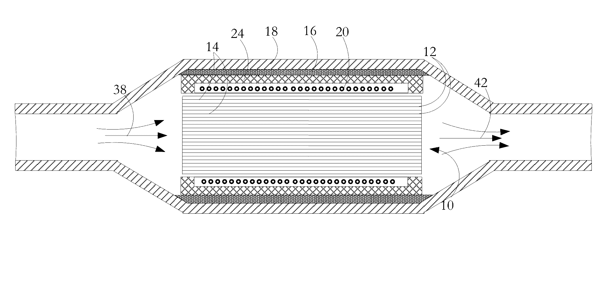
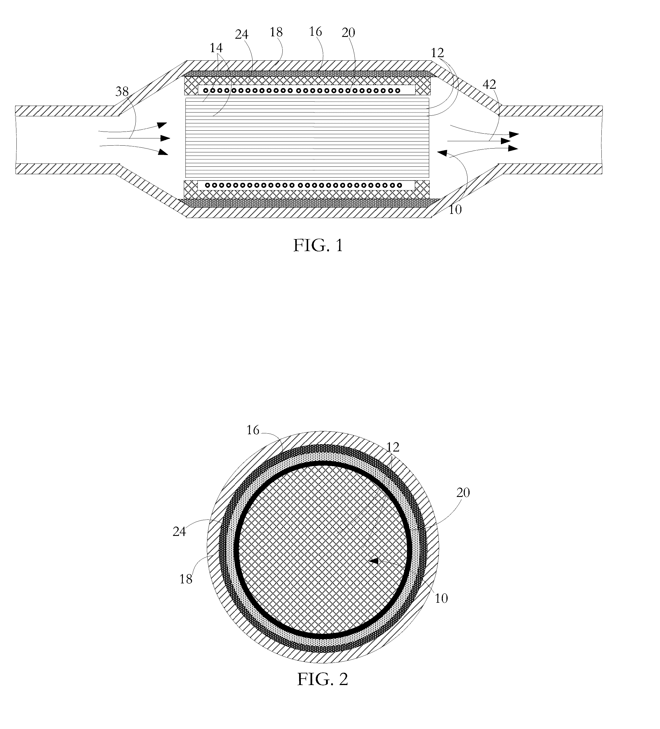
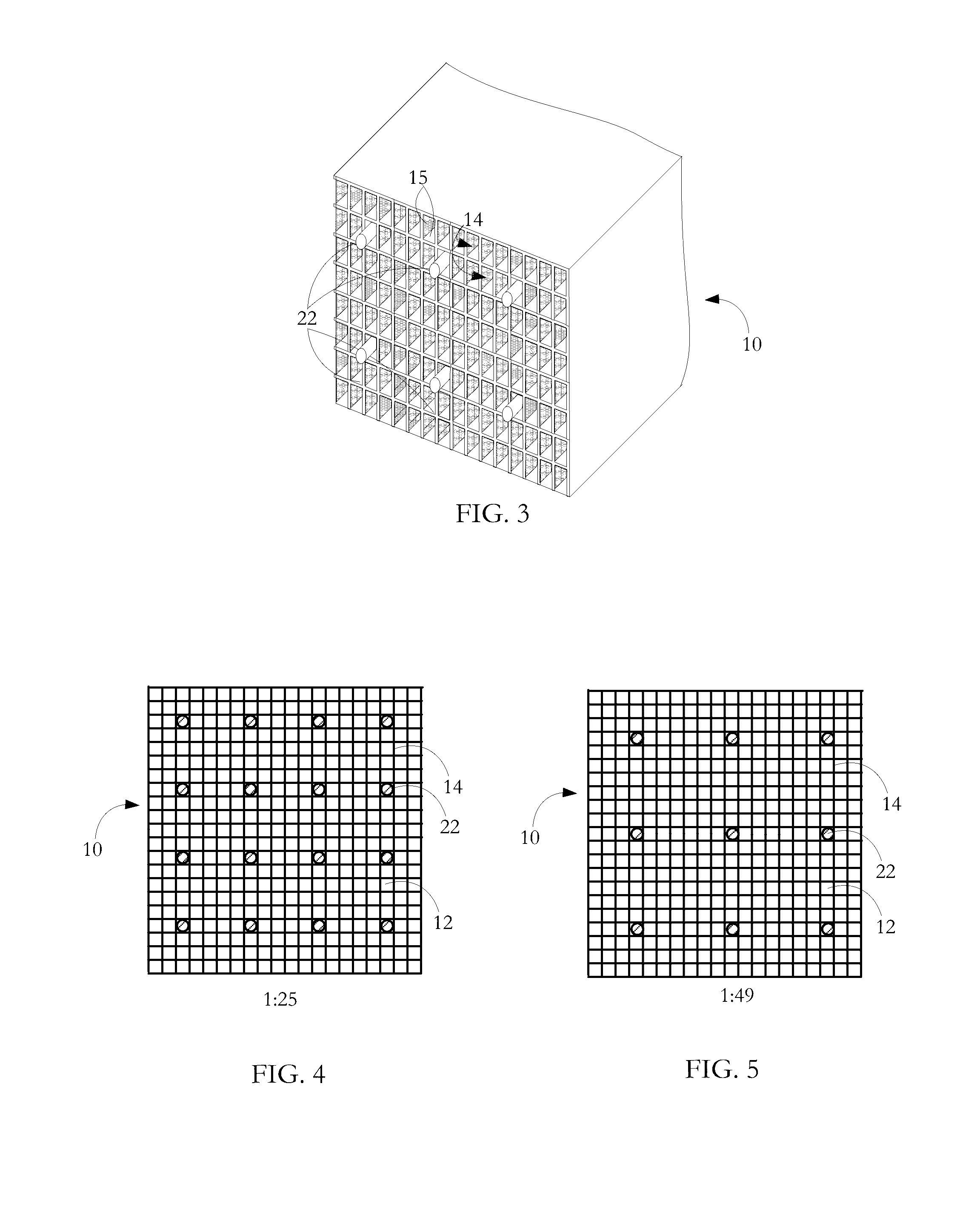
[0043]A gaseous emissions treatment assembly may take any of a number of forms. Typical of these is a catalytic converter having a cylindrical substrate body 10 usually made of ceramic material and often called a brick, an example of which is shown in FIG. 1. The brick has a honeycomb structure in which a number of small area passages or cells 12 extend the length of the brick, the cells being separated by walls. There are typically from 400 to 900 cells per square inch (cpsi) of cross-sectional area of the substrate body 10 and the walls are typically in the range 0.003 to 0.008 inches in thickness. Typically, the ceramic substrate body 10 is formed in an extrusion process in which green ceramic material is extruded through an appropriately shaped die and units are cut successively from the extrusion, the units being then cut into bricks. The areal shape of the cells or passages 12 may be whatever is convenient for contributing to the overall strength of the substrate body 10 while...


PUM

PropertyMeasurementUnit
temperatureaaaaaaaaaa
thicknessaaaaaaaaaa
temperatureaaaaaaaaaa

Abstract

An assembly for treating gaseous emissions includes a substrate body having cells for the passages of emissions gas. Lengths of metal wire are located in selected ones of the cells and an induction heating coil is mounted adjacent the substrate body for generating a varying electromagnetic field for inductive heating of the assembly including gaseous emissions passing along the cells. Within the cells, parts of the cell walls and parts of the wire surfaces are exposed to the passage of the gaseous emissions and both the cell wall parts and the wire surface parts have pollution treating catalyst at their surfaces.

Description

CROSS REFERENCE TO RELATED PATENTS[0001]The present application claims priority pursuant to 35 U.S.C. 119(e) from:[0002]U.S. Provisional Application Ser. No. 62234166 filed Sep. 29, 2015 entitled “Catalytic converter structures with directed induction heating”;[0003]U.S. Provisional Application Ser. No. 62258071 filed Nov. 20, 2015 entitled “Catalytic converter system with controlled induction heating and methods for use”;[0004]U.S. Provisional Application Ser. No. 62306885 filed Mar. 11, 2016 entitled “Structures for inductive heating”;[0005]U.S. Provisional Application Serial No. 62322719 filed Apr. 14, 2016 entitled “Induction heating structures”;[0006]The present application is a continuation in part of U.S. patent application Ser. No. 14452800 entitled “Catalytic converter structures with induction heating” filed Aug. 6, 2014 which claims priority pursuant to 35 U.S.C. 119(e) from[0007]U.S. Provisional Application Ser. No. 61879211 entitled “Catalytic converter employing electr...

Claims


Application Information

Patent Timeline
Patent Type & Authority Applications(United States)
IPC IPC(8): F01N3/20F01N3/28H05B6/10B01D53/94B01J35/04
CPCF01N3/2013B01D53/94B01D2255/915H05B6/108F01N3/2828B01J35/04F01N3/2026F01N2240/05F01N2510/00F01N3/2835F01N9/00F01N2900/0602Y02T10/12
Inventor CRAWFORD, ROBINDOUGLAS, JOHN
Owner ADVANCED TECH EMISSION SOLUTIONS
Why Eureka
Try Eureka