Eureka AIR delivers breakthrough ideas for toughest innovation challenges, trusted by R&D personnel around the world.

Material arrangement for fusion reactor and method for producing the same

Inactive Publication Date: 2017-01-26
AIRBUS DEFENCE & SPACE
View PDF1 Cites 0 Cited by
  • Summary
  • Abstract
  • Description
  • Claims
  • Application Information

AI Technical Summary

Benefits of technology

This patent aims to create a material arrangement for a fusion reactor that can hold large amounts of hydrogen and remains stable under reaction conditions. The goal is to develop a reliable method for producing this material arrangement. The technical effect would be the creation of a material arrangement that can store and hold large amounts of hydrogen in a stable state, allowing for its safe and reliable use in a fusion reactor.

Problems solved by technology

In this case these frequently lack demonstrable functionality and efficiency.
Difficulties arise here, in particular, from the fact that the carrier must be transported under constant boundary conditions such as, for example, vacuum, so that the hydrogen cannot volatilize from its condensed state.
The technical implementation of the method on an industrially usable apparatus can thus be very cumbersome.
Problematical here is the use of nanoparticles since, as a result of their reactivity, the effects on the environment have hitherto only been little clarified.
In particular, the re-use or removal of nickel as a poisonous heavy metal appears problematical in this patent specification.
These are either not sufficiently temperature-resistant under an oxygen atmosphere or are very brittle and therefore mechanically unstable.
Zirconium oxide ceramic, for example, is also not very stable in its pure form and is particularly affected by decomposition during use.
Furthermore, it is also not suitable to “survive” for long in a mechanically severely loaded environment with many vibrations.
Even transport has considerable risks with regard to the mechanical stability of the material.
Thus, a temperature range for a practicable fusion process can be limited.
Furthermore, the process control of a fusion process constitutes a problem of reaction delays.
If the process takes place too slowly or too weakly, this is unfavorable for the efficiency.
In addition, radioactive reaction channels can occur or neutrons can appear.

Method used


Image

  • Material arrangement for fusion reactor and method for producing the same
  • Material arrangement for fusion reactor and method for producing the same
  • Material arrangement for fusion reactor and method for producing the same

Examples


Embodiment Construction

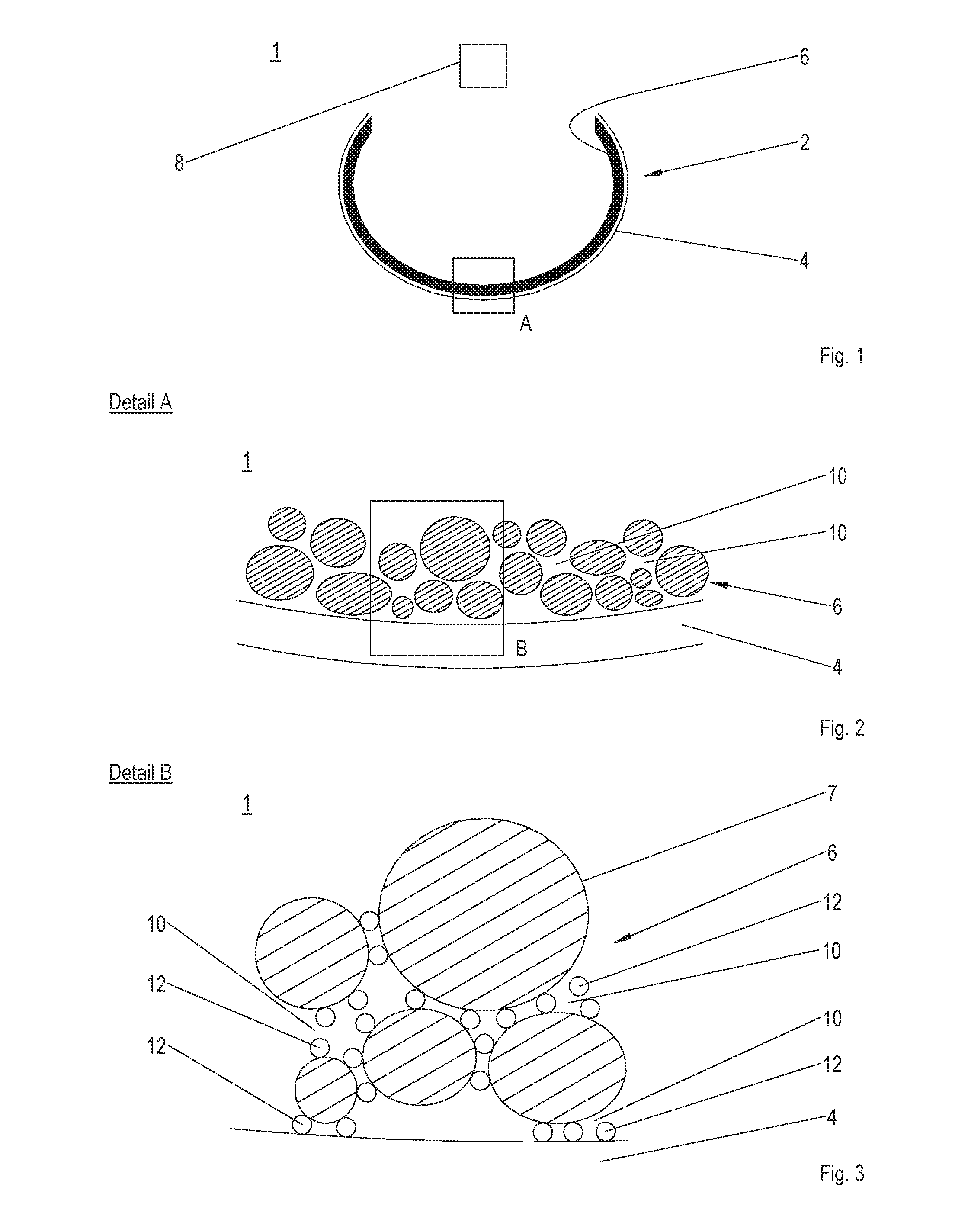
[0047]FIG. 1 shows a section through an exemplary embodiment of the apparatus 1 according to the invention for carrying out the method according to the invention for producing and for fusing ultra-dense hydrogen.

[0048]The apparatus 1 according to the exemplary embodiment comprises a cavity 2 which is open in places for receiving a gas. The gas here is preferably a hydrogen gas in its molecular form exposed to negative pressure, which is immediately converted into an atomic plasma in the cavity 2.

[0049]The cavity 2 is a pore of an open-pore metal foam or ceramic foam 4. The material of the metal foam or ceramic foam 4 should be selected in this case so that even while delivering the highest possible energy during a fusion, the material does not change its alpha lattice state or if this is changed, the alpha lattice state is achieved again.

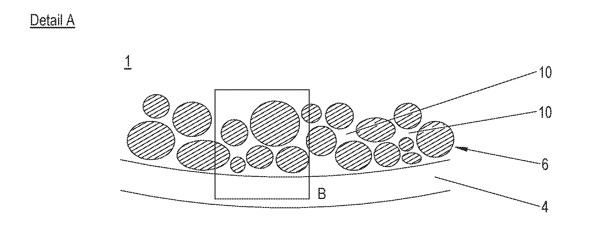
[0050]According to the exemplary embodiment, the pore of the metal foam 4 is at least partially provided with a catalyst coating 6 in the inner sid...


PUM

PropertyMeasurementUnit
Electrical resistanceaaaaaaaaaa
Mechanical propertiesaaaaaaaaaa
Superconductivityaaaaaaaaaa

Abstract

A material arrangement for a fusion reactor comprising at least one material which is configured as a foam-like carrier material for condensable binding and fusing of hydrogen. The carrier material is provided with positively charged vacancies for condensing hydrogen atoms, small pores for receiving the condensate and for accelerating the condensation after previous penetration of atoms or molecules into these, and large pores for transporting a catalyst into the small pores. Furthermore, a method for producing the material arrangement is disclosed.

Description

CROSS-REFERENCES TO RELATED APPLICATIONS[0001]This application claims the benefit of the German patent application No. 102015114749.1 filed on Sep. 3,2015 and of the German patent application No. 102015103843.9 filed on Mar. 16,2015, the entire disclosures of which are incorporated herein by way of reference.BACKGROUND OF THE INVENTION[0002]The invention relates to a material arrangement for a fusion reactor which is configured as a foam-like carrier material for condensable binding and fusing of hydrogen as well as to a method for producing the material arrangement.[0003]In many areas alternative energy sources are being sought which should, in particular, obviate the problems of energy sources based on nuclear reactions or fossil fuels. Here mention is usually made of fusion processes which should have the potential to be durable, environmentally friendly and reliable.[0004]In addition to hot fusion, various fusion processes in the field of cold fusion have already been described....

Claims


Application Information

Patent Timeline
IPC IPC(8): G21B1/19
CPCG21Y2004/101G21B1/19C01B3/02G21B3/00Y02E30/10Y02E60/32B01J8/0278B01J8/0285B01J21/063B01J2208/02C01B3/0031
Inventor KOTZIAS, BERNHARD
Owner AIRBUS DEFENCE & SPACE
Why Eureka
Eureka Blog
Learn More