Valve Cutter

a valve cutter and valve body technology, applied in the field of valve cutters, can solve the problems of increased risk of heart failure, restricted blood flow from the heart, obvious risks of such major surgery,

Active Publication Date: 2017-02-02
MCDONALD MICHAEL B
View PDF6 Cites 1 Cited by
  • Summary
  • Abstract
  • Description
  • Claims
  • Application Information

AI Technical Summary

Benefits of technology

[0007]For purposes of summarizing the invention, certain aspects, advantages, and novel features of the invention have been described herein. It is to be understood that not necessarily all such advantages may be achieved in accordance with any one particula

Problems solved by technology

Patients with aortic stenosis experience restricted blood flow from the heart and suffer increased risk of heart failure.
The drawbacks of the surgical approach include the obvious risks of such major surgery.
Drawbacks of the TAVR and balloon aortic valvulo

Method used


Image

  • Valve Cutter
  • Valve Cutter
  • Valve Cutter

Examples


Embodiment Construction

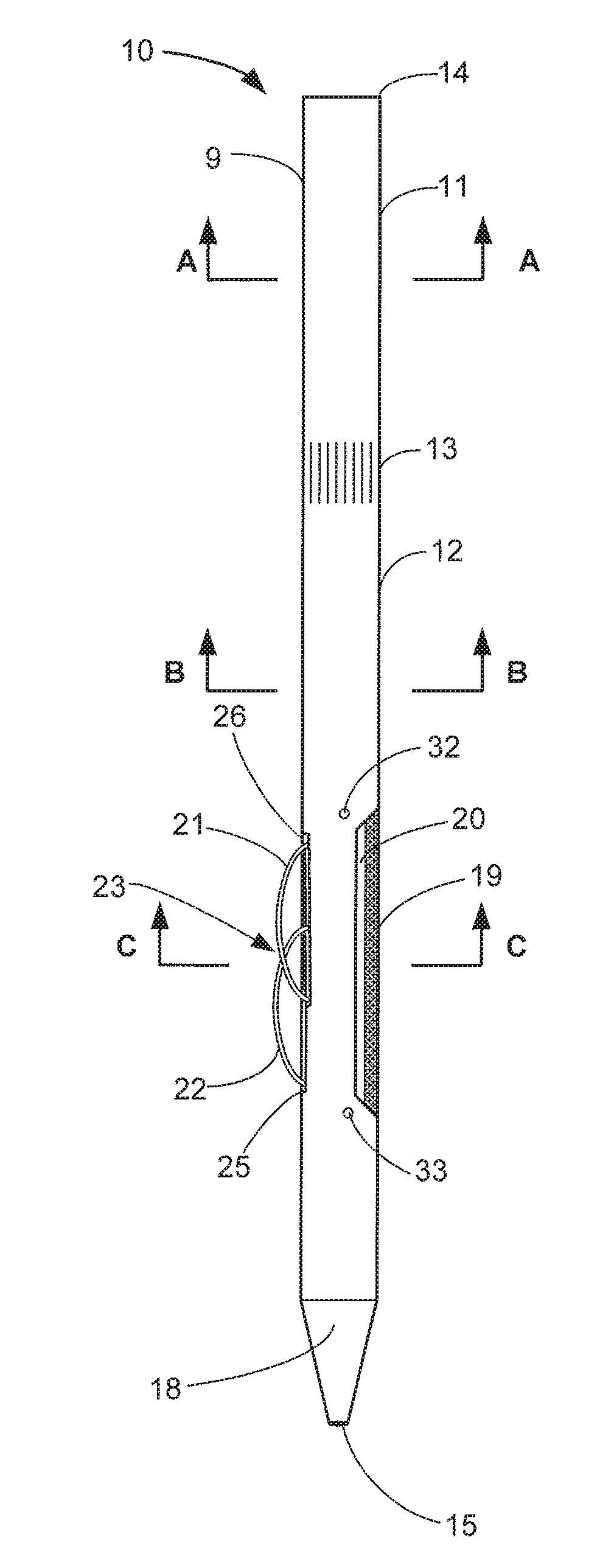
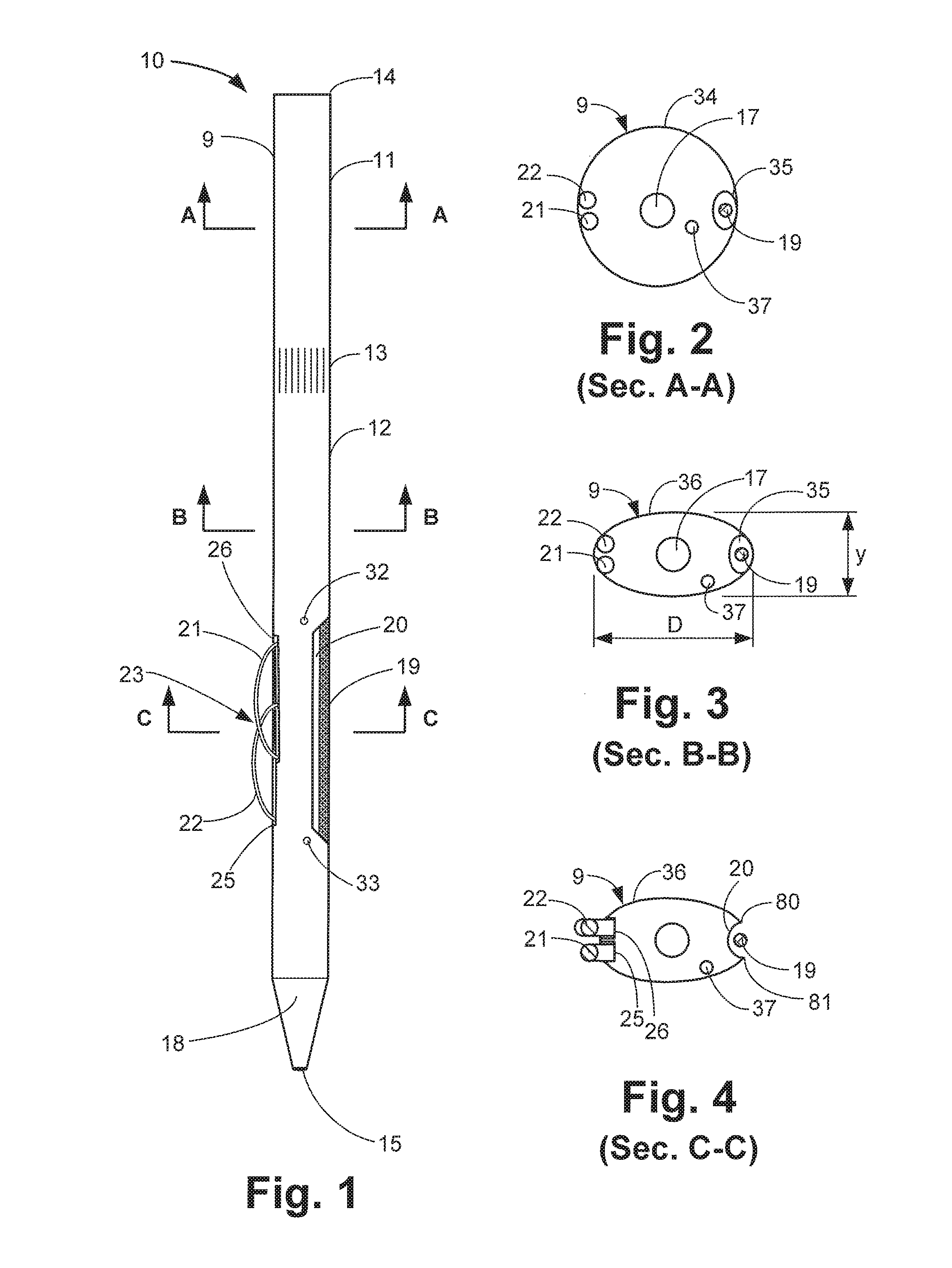
[0023]FIG. 1 is a front perspective view of an aortic valve cutter 10 according to an exemplary embodiment of the present disclosure. In this embodiment, the valve cutter 10 comprises an elongated housing 9 with a central lumen 17 (FIG. 2) extending through the housing 9 for receiving a guide wire (not shown). An upper opening (not shown) is disposed in an upper end 14 of the housing 9 and a lower opening (not shown) is disposed in a distal end 15 of the housing 9. The guide wire passes through the upper opening, the lumen, and the lower opening. The lumen 17 and openings allow the cutter 10 to be advanced through an artery and across the aortic valve in an over-the-wire fashion.

[0024]In the illustrated embodiment, the housing 9 is formed in one piece from flexible material such as the tubing currently used to form cardiac catheters. The housing 9 comprises a generally cylindrical upper portion 11 and a generally elliptical lower portion 12. A transition portion 13 transitions the h...


PUM


Abstract

A cardiac valve cutter of the present disclosure has a flexible housing with a central lumen for receiving a guide wire. A high-speed cutting blade is disposed within the housing near an edge of the housing. A trough cut into a side of the housing exposes a portion of the cutting blade so that the cutting blade can cut valve tissue. Two pusher wires are disposed on an opposite side of the housing from the cutting blade. Troughs cut into the side of the housing form openings from which the pusher wires can extend. The pusher wires are staggered with respect to one another in the longitudinal direction. When the pusher wires are advanced, they extend outwardly from the troughs and can be used to stabilize the cutter at the cardiac valve and push the cutting blade against the valve on the opposite side.

Description

CROSS REFERENCE TO RELATED APPLICATIONS[0001]This application is a continuation-in-part of U.S. Non-provisional Application Ser. No. 14 / 097,874 titled “Aortic Valve Cutter, flied on Dec. 5, 2013, which application claims priority to U.S. Provisional Application Ser. No. 61 / 733,803, titled “Aortic Valve Cutter,” filed on Dec. 5, 2012. The entire contents of U.S. Non-provisional Application Ser. No. 14 / 097,874 and U.S. Provisional Application Ser. No. 61 / 733,803 are herein incorporated by reference.BACKGROUND AND SUMMARY OF THE INVENTION[0002]Aortic stenosis, an abnormal narrowing of the aortic valve, is the most common valve disease in the world. Patients with aortic stenosis experience restricted blood flow from the heart and suffer increased risk of heart failure. Currently available treatments for aortic stenosis include surgical valve replacement, transcatheter valve replacement, and balloon aortic valvuloplasty. In surgical valve replacement, the patient undergoes open heart sur...

Claims


Application Information

Patent Timeline
IPC IPC(8): A61B17/32A61M29/00
CPCA61B17/32002A61B2017/320028A61M29/00A61B17/320758A61B17/320783A61B2017/22071A61B2017/22097A61B2017/320004A61B2090/064
Inventor MCDONALD, MICHAEL B.
Owner MCDONALD MICHAEL B
Why Eureka
Try Eureka