Working Vehicle

a technology for working vehicles and lifting devices, applied in adaptive control, servomotors, instruments, etc., can solve the problems of insufficient improvement of operating efficiency under automatic excavation, delay in the timing of control start, and inability to start auto lift control or auto tilt control at optimal timing, etc., to achieve the effect of increasing the bottom pressur

Active Publication Date: 2017-02-09
KOMATSU LTD
View PDF1 Cites 16 Cited by
  • Summary
  • Abstract
  • Description
  • Claims
  • Application Information

AI Technical Summary

Benefits of technology

[0005]In addition to the excavation work, the wheel loader sometimes performs a grading work (e.g., ground leveling), which also increases the bottom pressure. Accordingly, the wheel loader needs to be set not to start the automatic excavation control in response to an increase in the bottom pressure during the grading work.

Problems solved by technology

However, when the threshold is set high, the auto lift control or the auto tilt control cannot be started until the bottom pressure reaches a high value, which results in delay of the timing of the start of the control.
The control cannot thus be started until a bucket-thrusting distance relative to an object such as soil and sand becomes large, so that the auto lift control or the auto tilt control cannot be started at an optimal timing.
Consequently, an operating efficiency cannot be sufficiently improved under the automatic excavation control.

Method used


Image

  • Working Vehicle
  • Working Vehicle
  • Working Vehicle

Examples


Embodiment Construction

)

[0030]An exemplary embodiment of the invention will be described below with reference to the attached drawings.

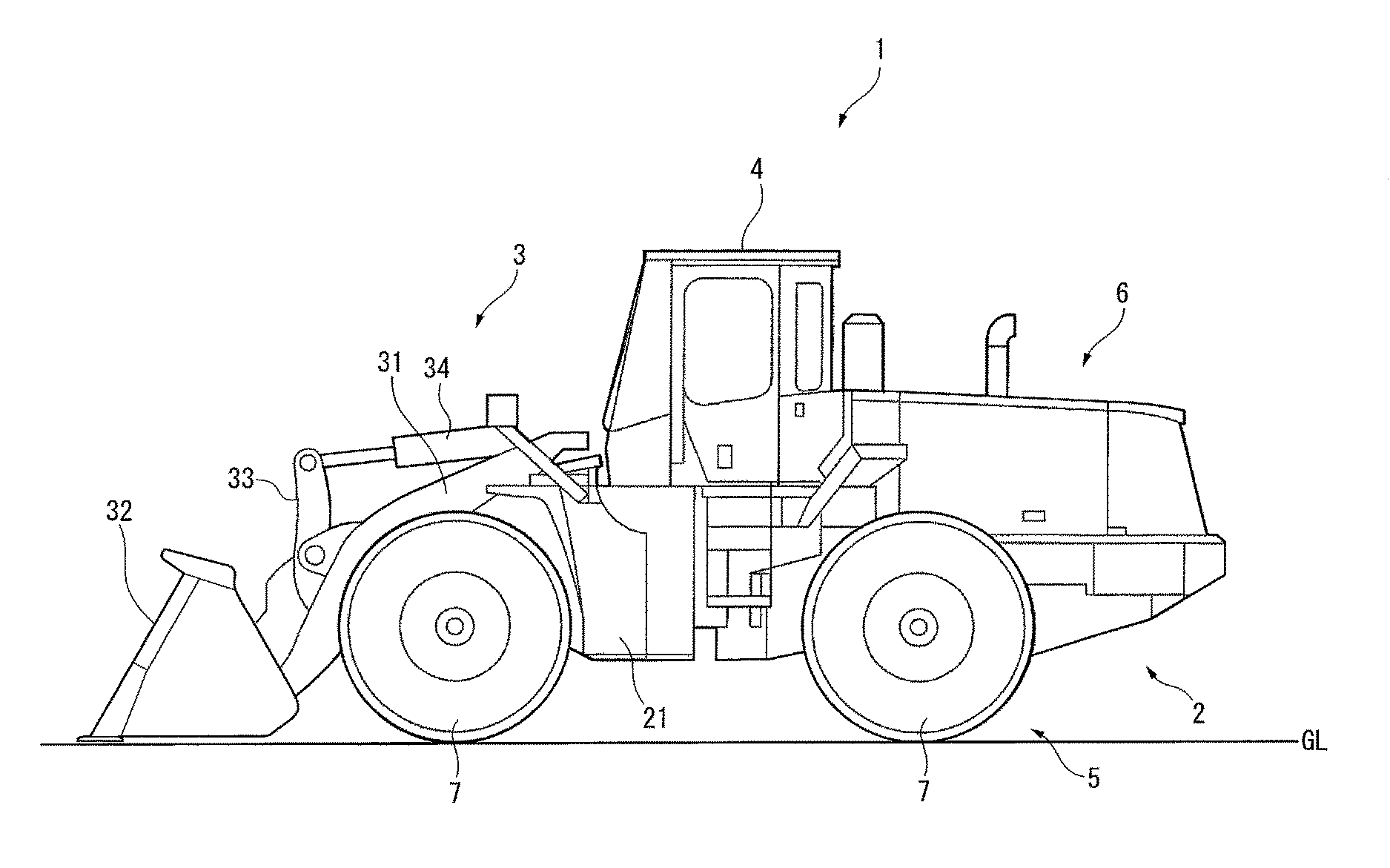
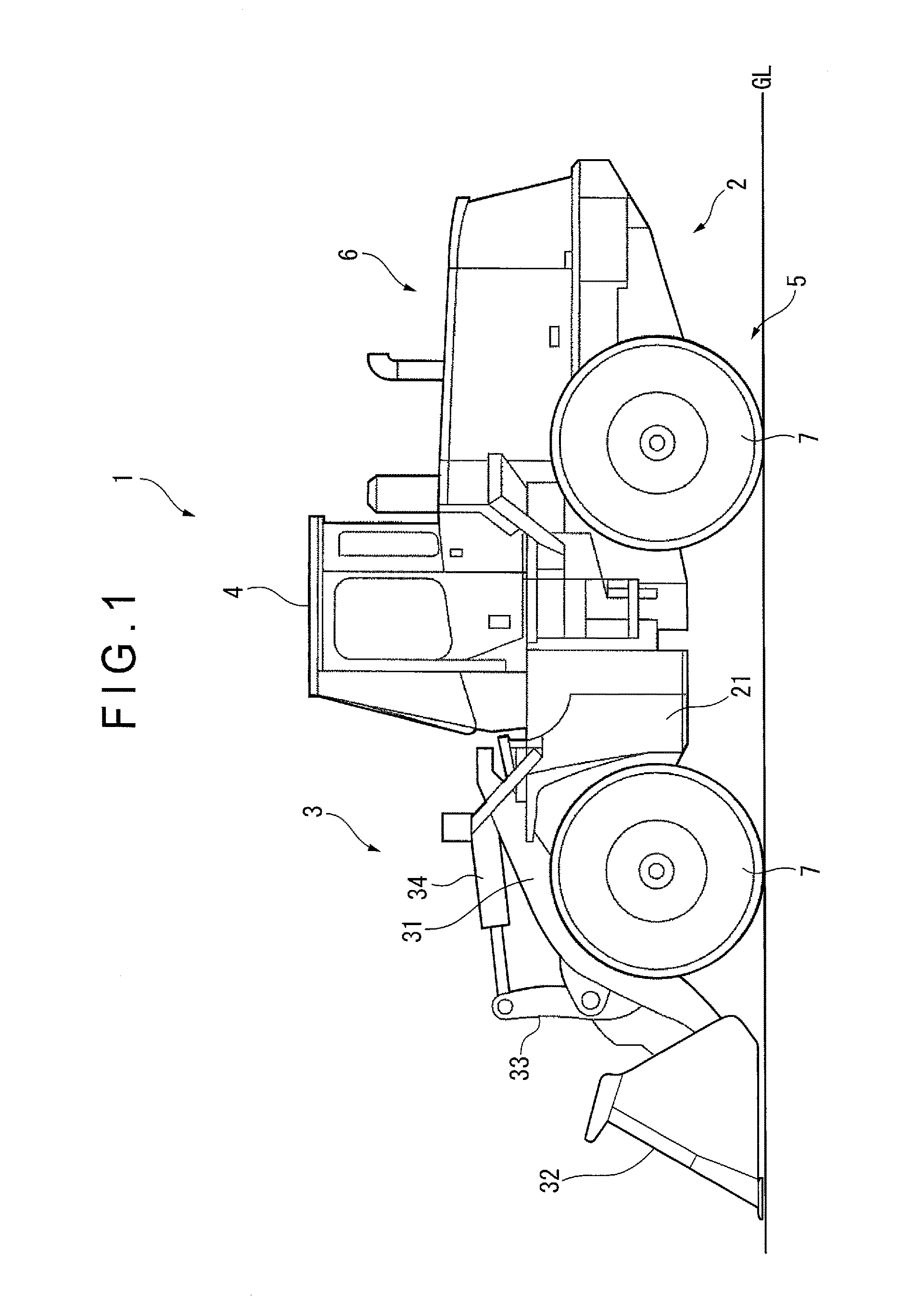
[0031]FIG. 1 is a side view showing a wheel loader 1 (working vehicle) according to the exemplary embodiment. It should be noted that, in the figures, directions are determined with reference to an operator in an operating state for the wheel loader 1. Specifically, a vehicle front-rear direction is simply referred to as a front-rear direction, a vehicle width direction is referred to as a right-left direction, and a vehicle up-down (vertical) direction is simply referred to as an up-down (vertical) direction. Further, an innermost of the bucket means a rear side relative to a bucket opening.

Description of Overall Arrangement of Wheel Loader

[0032]As shown in FIG. 1, the wheel loader 1 includes a vehicle body 2, working equipment 3, a cab 4, a travel device 5, and a power unit 6.

[0033]The vehicle body 2 includes a steel front vehicle body frame 21 that supports the working ...


PUM


Abstract

A working vehicle (1) includes: a vehicle body (2); and a boom (31); a bucket (32); a boom driving unit including a boom cylinder (36); a bucket driving unit configured to swing the bucket (32); a boom-bottom pressure sensor (460) configured to detect a boom-bottom pressure of the boom cylinder (36); and a working equipment controller (10) configured to control at least one of a lift motion of the boom (31) and a tilt motion of the bucket (32). The bucket (32) includes an inclined portion (44). The working equipment controller (10) controls the lift motion or the tilt motion by comparing a threshold set in accordance with an inclination angle of the inclined portion (44) with the boom-bottom pressure.

Description

TECHNICAL FIELD[0001]The present invention relates to a working vehicle.BACKGROUND ART[0002]A working vehicle is provided with working equipment for loading, for instance, soil and sand or crushed rocks onto a dump truck or the like. Such a working vehicle may be a wheel loader. The wheel loader is a bucket-equipped vehicle configured to travel using tires. In order to reduce a burden on an operator in performing an excavation work using the wheel loader, a motion of the bucket may be automatically controlled to excavate (see, for instance, Patent Literature 1).[0003]In the automatic excavation control disclosed in Patent Literature 1, when a bottom pressure, which is a pressure of a hydraulic oil supplied to a boom hydraulic cylinder, a driving speed of the working vehicle and a boom angle satisfy auto lift start conditions, an auto lift control of a boom is started. Similarly, when the bottom pressure of the boom hydraulic cylinder and the driving speed of the working vehicle sati...

Claims


Application Information

Patent Timeline
Patent Type & Authority Applications(United States)
IPC IPC(8): E02F3/43F15B11/20E02F3/40F15B11/16E02F3/28E02F3/42
CPCE02F3/431E02F3/283F15B11/20E02F3/40F15B11/161E02F3/422E02F3/434E02F3/437E02F9/265G05B13/0255E02F3/43
Inventor WADA, MINORUOHTA, TOSHIYUKIHONDA, TOSHIMITSUTSUTSUMI, KATSUHIROKOBAYASHI, TAKAYAYAMAGOE, YOSUKE
Owner KOMATSU LTD
Why Eureka
Try Eureka