Supersulf- a process with internal cooling and heating reactors in subdewpoint sulfur recovery and tail gas treating systems

a technology of internal cooling and heating reactors, which is applied in the direction of sulfur compounds, sulfur preparation/purification, and separation processes, etc., can solve the problems of high capital cost of the building tail gas unit, difficult operation of the sulfur plant, and ineffective cost effectiveness, so as to achieve small capacity, reduce capital cost, and reduce the effect of sulfur recovery

Active Publication Date: 2017-02-16
RAMESHNI MAHIN +1
View PDF0 Cites 26 Cited by
  • Summary
  • Abstract
  • Description
  • Claims
  • Application Information

AI Technical Summary

Benefits of technology

[0052](7) In accordance with this innovation; the SuperSulf reactors achieve much higher sulfur recovery compare to any commercial technology in the market, for smaller capacity sulfur recovery, the tail gas ca...

Problems solved by technology

Sulfur plant operation is a very complicated and challenging job.
The capital cost of the building tail gas unit is very close to the cost of building a modified conventional Claus unit considering for using it to recover only the remaining sulfur compounds which, were not recovered in the Claus unit, the fact is that it is not cost effective.
In addition about 8-12 (2 ways or 3 ways) switching valves required and they are located on the main process lines containing toxic gases as the process requirement which leakage of these valves are major safety concerns and problems...

Method used


Image

  • Supersulf- a process with internal cooling and heating reactors in subdewpoint sulfur recovery and tail gas treating systems
  • Supersulf- a process with internal cooling and heating reactors in subdewpoint sulfur recovery and tail gas treating systems
  • Supersulf- a process with internal cooling and heating reactors in subdewpoint sulfur recovery and tail gas treating systems

Examples


Embodiment Construction

[0061]One or more illustrative embodiments incorporating the invention disclosed herein are presented below. Not all features of an actual implementation are described or shown in this application for the sake of clarity. It is understood that in the development of an actual embodiment incorporating the present invention, numerous implementation-specific decisions must be made to achieve the developer's goals, such as compliance with system-related, business-related, government related and other constraints, which vary by implementation and from time to time. While a developer's efforts might be complex and time-consuming, such efforts would be, nevertheless, a routine undertaking for those of ordinary skill the art having benefit of this disclosure.

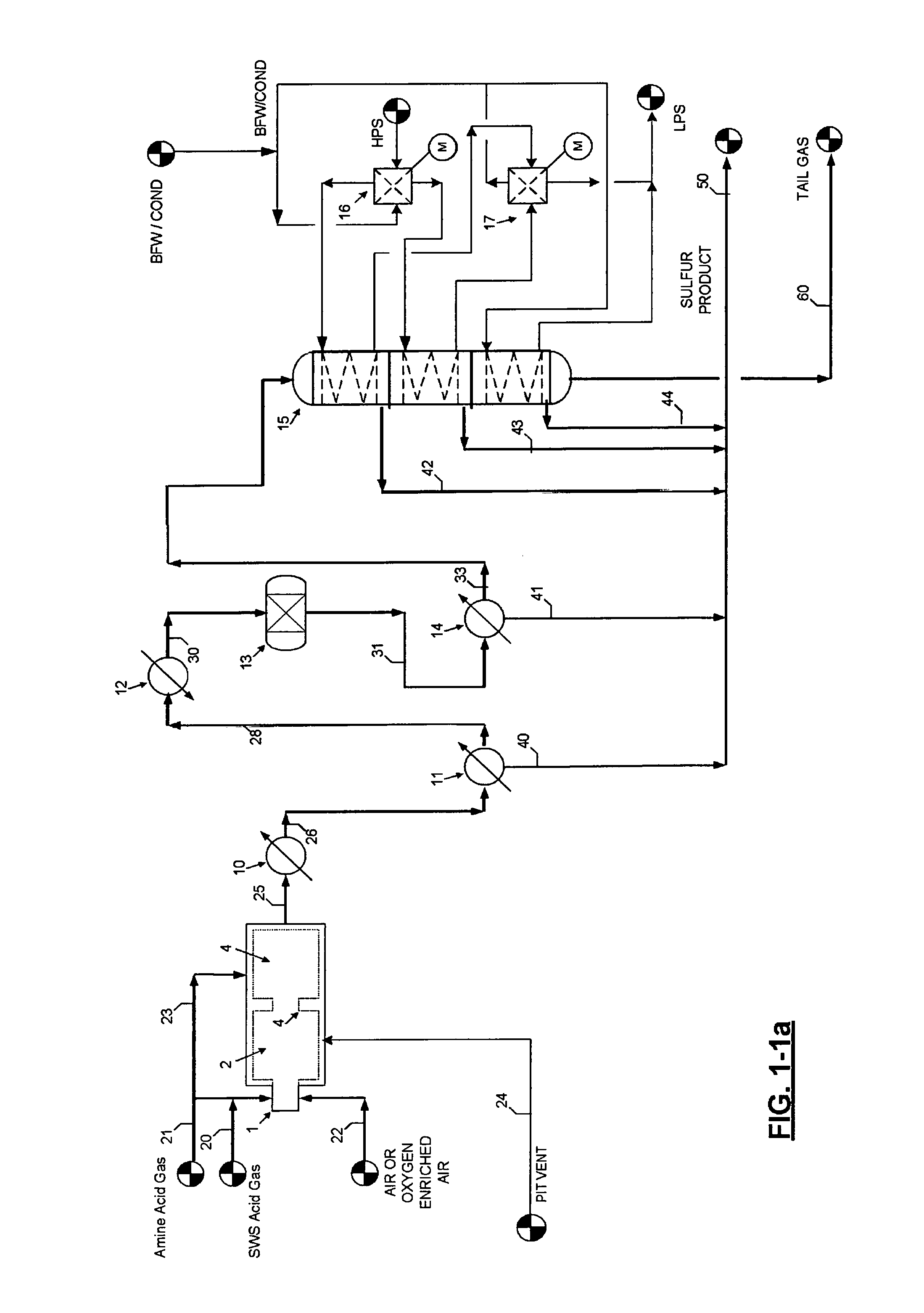
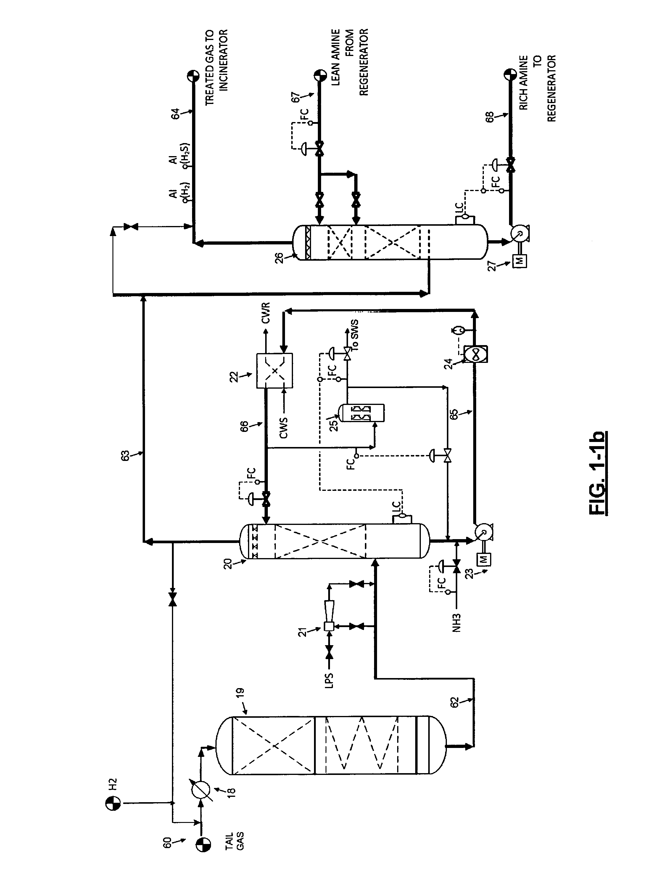
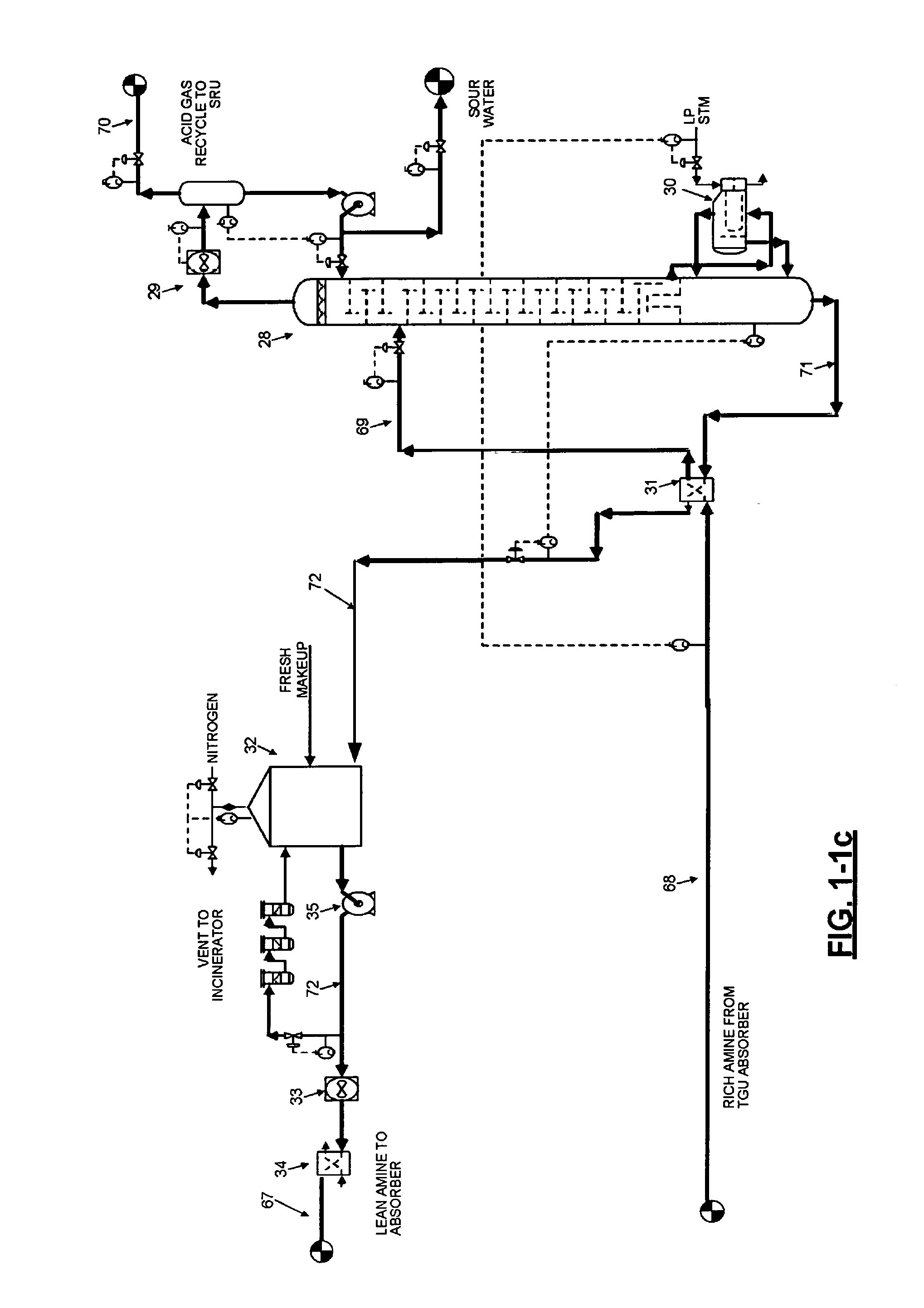
[0062]In general terms, Applicant has created new processes for the conversion of sulfur compounds to elemental sulfur using SuperSulf SubDewPoint reactors consists of internal cooling and internal heating thermoplate exchangers filled b...


PUM

PropertyMeasurementUnit
Temperatureaaaaaaaaaa

Abstract

SuperSulf process refers to an innovative reactor design consisting of internal cooling and heating thermoplate exchangers where it is filled by the Claus type catalysts between plates in the SRU and hydrogenation catalysts in the tail gas unit. SuperSulf reactor consists of 3 reactor zones in the sulfur recovery which operates as a SubDewPoint process where the mode of operation are controlled by switching valves on the utilities streams high pressure steam and high quality water and steam where the first 2 zones operate as hot and cold and switches to cold and hot where the produced sulfur is condensed. The third zone operates as cold all the time where consists of the last sulfur condenser by producing Low pressure steam. The tail gas unit consists of 2 reactor zones of hydrogenation reactor and hydrolysis reactor with internal plate cooling then followed by the tail gas amine with a selective solvent. The thermal incineration system can meet less than 50 ppmv of SO2 and with caustic incineration less than 10 ppmv of SO2 resulting zero emission.

Description

CROSS REFERENCE TO RELATED APPLICATIONS[0001]Not ApplicableSTATEMENT REGARDING FEDERALLY SPONSORED RESEARCH OR DEVELOPMENT[0002]Not ApplicableREFERENCE TO SEQUENCE LISTING[0003]Not ApplicableREFERENCE TO A TABLE[0004]Not ApplicableREFERENCE TO A COMPUTER PROGRAM LISTING COMPACT DISK APPENDIX[0005]Not ApplicableBACKGROUND OF THE INVENTION[0006]This disclosure relates generally to Processes for the conversion of the sulfur compounds to elemental sulfur through reactors equipped with internal cooling and heating thermoplate exchangers as SuperSulf reactors. The SuperSulf reactor is located after the reaction furnace of the Claus unit with air or oxygen operation. After the thermal section of the Claus; the first catalytic stage shall be the conventional Claus reactor consists of alumina and titanium catalysts. The second stage is a 3 zone SubDewPoint reactor equipped with internal heating and cooling thermoplate exchangers. The switching valves are located on the water and steam utilit...

Claims


Application Information

Patent Timeline
IPC IPC(8): C01B17/04
CPCC01B17/0456B01D53/1468B01D53/1481B01D2252/204C01B17/164
Inventor RAMESHNI, MAHINSANTO, STEPHEN L.
Owner RAMESHNI MAHIN
Why Eureka
Try Eureka