Apparatus and System for Boosting, Transferring, Turning and Positioning a Patient

a technology for transferring, positioning, and boosting a patient, which is applied in the direction of mechanical equipment, functional valve types, transportation and packaging, etc., and can solve the problems of skin being more fragile and therefore more susceptible to damage, the risk of pressure ulceration (bed sores), and the risk of tissue death

Active Publication Date: 2017-02-23
SAGE PRODS
View PDF0 Cites 20 Cited by
  • Summary
  • Abstract
  • Description
  • Claims
  • Application Information

AI Technical Summary

Benefits of technology

[0010]Aspects of the present disclosure relate to a system for use with a bed having a frame and a supporting surface supported by the frame, which includes an inflatable patient support device. The device includes a top sheet and a bottom sheet, where the top sheet is connected to the bottom sheet to define a cavity configured to be inflated, such that the top sheet forms a top wall of the cavity in use, and the bottom sheet forms a bottom wall of the cavity in use. The device further has a plurality of passages extending from the cavity to an exterior of the device, through the bottom sheet, and a plurality of gussets connected to the top sheet and the bottom sheet and extending across the cavity. The passages are configured to permit air to pass from the cavity to the exterior of the device and to flow between a bottom surface of the device and a supporting surface upon which the device is configured to rest. This airflow reduces friction between the device and the surface on which the device rests. The gussets may serve to limit inflation of the device and at least partially define the shape and contour of the device when inflated.
[0013]According to a further aspect, the device further includes a piece of air-permeable material connected to the bottom surface of the device and positioned to cover at least one of the passages, and wherein the piece of air-permeable material is configured to allow air passing through the passage(s) to escape to the exterior of the device. In one configuration, the piece of air-permeable material may have directional friction properties, e.g., being configured to provide greater resistance to sliding of the device with respect to the supporting surface in at least one direction as compared to at least one other direction.
[0032]According to another aspect, the method may include inserting a wedge or wedges as described herein beneath the device and beneath the patient by moving the wedge away from a side edge of the bed and toward and under the patient. After insertion, the ramp surface of the wedge supports the patient in an angled position. The ramp surface of the wedge may have an engagement member that engages the bottom surface of the device (e.g., another engagement member on the device) to form a selective gliding assembly that resists movement of the device in a first direction away from the side edge of the bed and / or from the back wall toward the front end of the wedge, and permits movement of the device in a second direction toward the side edge of the bed and / or from the front end toward the back wall, such that a first pull force necessary to create sliding movement of the wedge in the first direction is greater compared to a second pull force necessary to create sliding movement of the wedge in the second direction. This permits the wedge to be inserted underneath the device, but resists the device sliding down the ramp surface of the wedge. Additionally or alternately, the base wall of the wedge may have an engagement member that engages a surface of the bed to form a selective gliding assembly that resists movement of the wedge with respect to the surface of the bed in a first direction away from the patient and toward the side edge of the bed, and permits movement of the wedge with respect to the surface of the bed in a second direction from the side edge of the bed toward the patient to ease insertion of the wedge beneath the device, such that a first pull force necessary to create sliding movement of the wedge in the first direction is greater compared to a second pull force necessary to create sliding movement of the wedge in the second direction. The device (along with the patient) may be pulled slightly toward the side edge of the bed to properly position the patient after insertion of the wedge.

Problems solved by technology

These patients are dependent upon nurses / caregivers to move, and are at risk of forming pressure ulcers (bed sores) due to their inability to move.
Pressure ulcers develop due to pressure on a patient's skin for prolonged periods of time, particularly over areas where bone or cartilage protrudes close to the surface of the skin because such pressure reduces blood flow to the area eventually resulting in tissue death.
The risk of forming a pressure ulcer is exacerbated by skin surface damage caused by frictional forces and shearing forces resulting from the patient's skin rubbing or pulling against a surface and excessive heat and moisture, which causes the skin to be more fragile and therefore more susceptible to damage.
Furthermore, skin in the sacral region is often more susceptible to damage due to shear and friction resulting from the patient being pushed or pulled over the surface of the mattress to reposition him / her, or from sliding down over the surface of the bed when positioned with his / her upper body in an inclined position for pulmonary reasons.
Existing devices and methods often do not adequately protect against pressure ulcers in bedridden patients, particularly pressure ulcers in the sacral region.
However, there are several barriers to compliance with this type of protocol, resulting in patients not being turned as often as necessary, or positioning properly at a side-lying angle, to prevent pressure ulcers.
First, turning patients is difficult and time consuming, typically requiring two or more caregivers.
Second, pillows are often stuffed partially under the patient to support the patient's body in resting on his or her left or right side; however, pillows are non-uniform and can pose difficulties in achieving consistent turning angles, as well as occasionally slipping out from underneath the patient.
Third, patients who are positioned in an inclined position on the bed often slide downward toward the foot of the bed over time, which can cause them to slip off of any structures that may be supporting them.
Additionally, this requires the nurse / caregiver to frequently “boost” the patient back up to the head of the bed, which, like turning, can be difficult and time-consuming, and once again may result in shearing / friction of the patient's skin.
Further, many patient positioning devices cannot be left under a patient for long periods of time, because they do not have sufficient breathability and / or compatibility with certain bed functions such as low-air loss (LAL) technology and can be easily stained when soiled.
Moreover, caregivers often need to move patients to or from a bed surface for transport, treatment, or examination of the patient.
The process may be complicated by the size of the patient, the patient's level of disability, and / or the patient's state of consciousness.
In addition to being difficult and time-consuming, turning, positioning, transferring and / or boosting patients, types of “patient handling” activities, can result in injury to healthcare workers who push, pull, or lift the patient's body weight.
For healthcare workers, the most prevalent cause of injuries resulting in days away from work is overexertion or bodily reaction, which includes motions such as lifting, bending, or reaching and is often related to patient handling.
These injuries can be sudden and traumatic, but are more often cumulative in nature, resulting in gradually increasing symptoms and disability in the healthcare worker.

Method used


Image

  • Apparatus and System for Boosting, Transferring, Turning and Positioning a Patient
  • Apparatus and System for Boosting, Transferring, Turning and Positioning a Patient
  • Apparatus and System for Boosting, Transferring, Turning and Positioning a Patient

Examples


Embodiment Construction

[0063]While this invention is capable of embodiment in many different forms, there are shown in the drawings, and will herein be described in detail, certain embodiments of the invention with the understanding that the present disclosure is to be considered as an example of the principles of the invention and is not intended to limit the broad aspects of the invention to the embodiments illustrated and described.

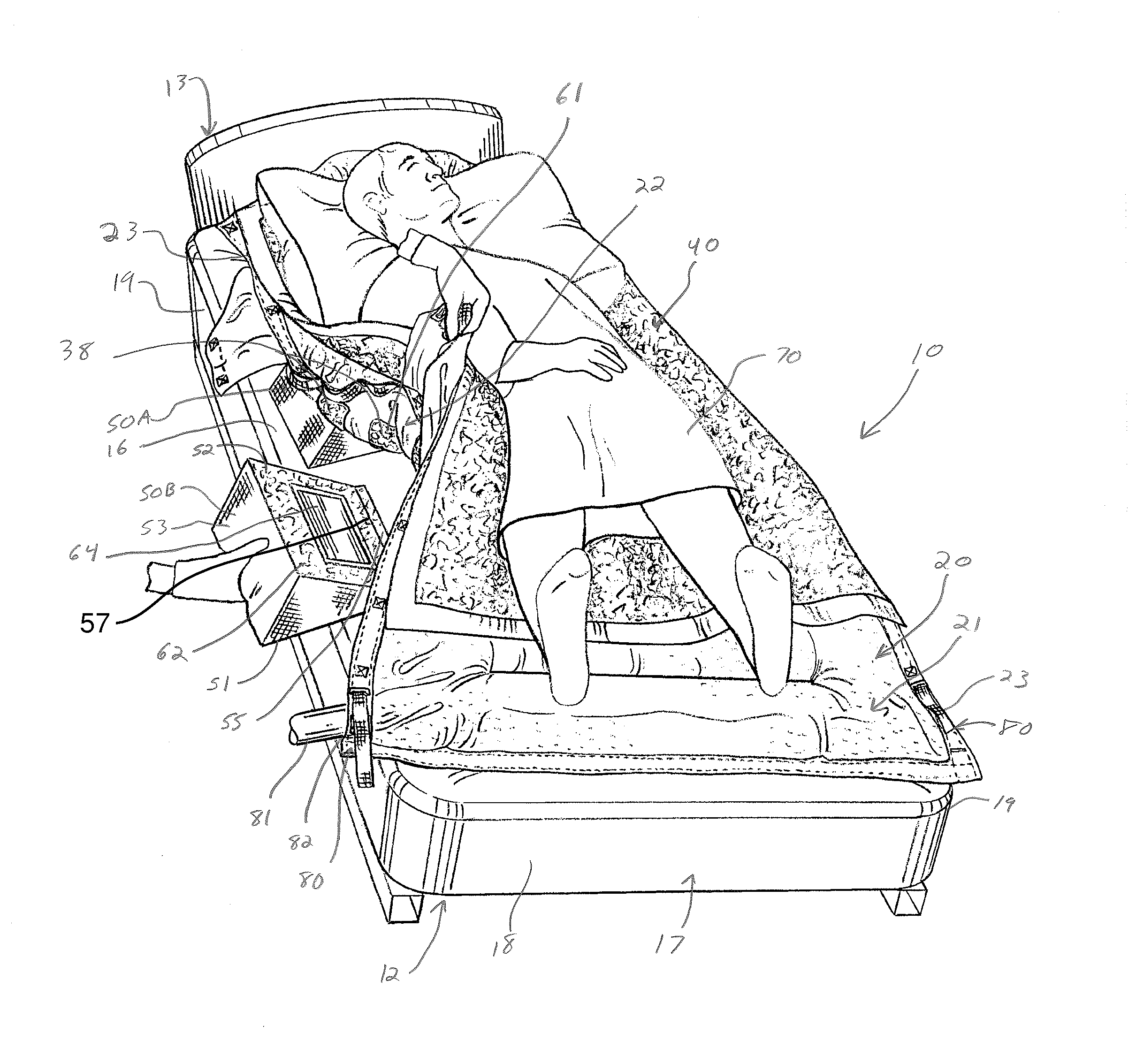
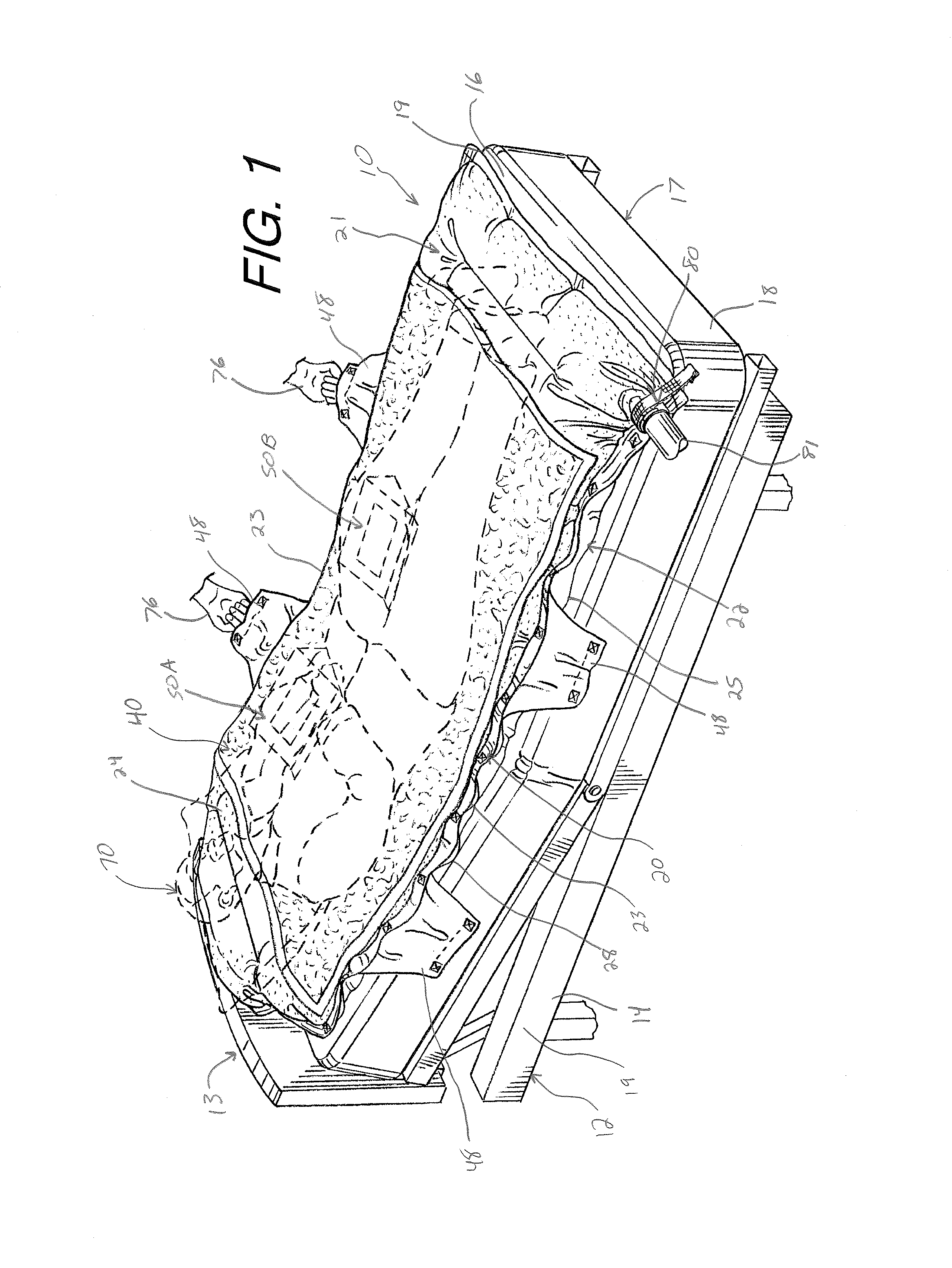
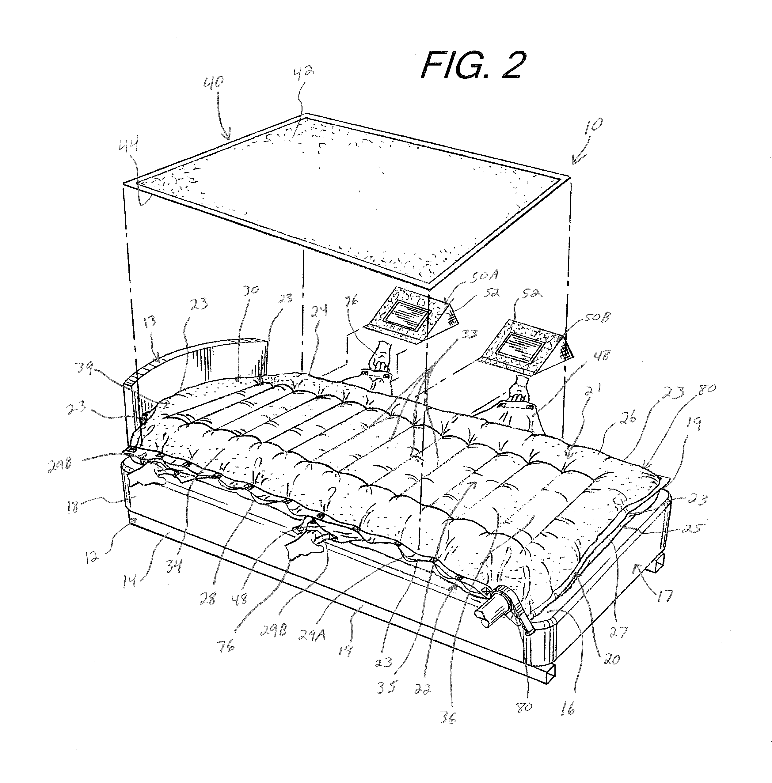
[0064]In general, the disclosure relates to a system or apparatus, including an inflatable patient support device, an absorbent body pad configured to be placed over the device, and one or more wedges configured to be placed underneath the device to support the patient in various positions, where the wedge(s) and the device form one or more selective gliding assemblies, as well as systems including one or more of such devices and methods utilizing one or more of such systems and / or devices. Various embodiments of the invention are described below.

[0065]Referring now to the f...


PUM


Abstract

A patient positioning system for use with a patient on a bed includes an inflatable patient support device, and optionally, other components such as one or more wedges and / or an absorbent pad. The device includes top and bottom sheets, where the top sheet is connected to the bottom sheet to define a cavity, such that the top and bottom sheets form top and bottom walls of the cavity in use. The device further has passages extending from the cavity to an exterior of the device, through the bottom sheet, and gussets connected to the top and bottom sheets and extending across the cavity. The passages permit air to pass from the cavity to the exterior of the device and to flow between the bottom surface of the device and the surface supporting the device. Selective glide assemblies may be used to resist sliding of these components in certain directions.

Description

TECHNICAL FIELD[0001]The present invention generally relates to an apparatus, system, and method for boosting, transferring, turning, and positioning a person on a bed or the like, and, more particularly, to an inflatable patient support device having a gripping surface, an absorbent pad, and / or a wedge for use in turning and positioning a person, utilizing airflow, high and low friction surfaces to transfer or boost, and selective glide assemblies to allow, assist, or resist movement of the components of the system in certain directions, as well as systems and methods including one or more of such apparatuses.BACKGROUND[0002]Nurses and other caregivers at hospitals, assisted living facilities, and other locations often care for patients with limited or no mobility, many of whom are critically ill or injured and / or are bedridden. These patients are dependent upon nurses / caregivers to move, and are at risk of forming pressure ulcers (bed sores) due to their inability to move. Pressur...

Claims


Application Information

Patent Timeline
Patent Type & Authority Applications(United States)
IPC IPC(8): A61G7/057A61G7/10A61G7/00
CPCA61G7/05715A61G7/001A61F2013/15154A61G7/05769A61G7/1021A61G1/01A61G7/1028F16K15/20
Inventor RIGONI, MICHAEL J.SWEETWOOD, GARRETT W.FOWLER, PAUL M.DAVIS, GREGORY T.KENNEDY, JEFFREY A.HANIFL, PAUL H.
Owner SAGE PRODS
Why Eureka
Try Eureka