Light weight cordless stud welder

a cordless, stud welder technology, applied in the field of stud welders, can solve the problems of difficult transportation and operation of the portable stud welder system, large and heavy welding system, and inability to be portable, so as to achieve convenient transportation and operation, and quickly and easily disassemble the

Active Publication Date: 2017-02-23
NELSON STUD WELDING
View PDF15 Cites 8 Cited by
  • Summary
  • Abstract
  • Description
  • Claims
  • Application Information

AI Technical Summary

Benefits of technology

[0009]The invention in its broadest aspect therefore provides a cordless, portable stud welder apparatus that can be easily transported and operated, even while being manually carried and supported by an operator. More specifically, the use of a lithium ion battery provides a light weight, compact design which does not require a bulky thermal management system to keep the apparatus cool, nor does it require an integral power cord to operate or re-charge. Furthermore, the portable stud welder apparatus may advantageously be used even while a battery is charging since the lithium ion battery is quickly and easily disconnected from the housing and replaced with another battery.

Problems solved by technology

However, the stud welder systems disclosed in US 2013 / 0126498 and US 2013 / 0062327 each must be tethered to an external power supply during operation, and thus are not portable.
While other stud welder systems are battery-powered to improve on the portability of stud welder systems, each of these portable systems rely on multiple lead acid batteries, resulting in a relatively large and heavy welding system.
Put another way, even if portable, the use of lead acid batteries causes the portable stud welder system to be difficult to transport and operate, especially when support by a user is required during welding.
Since the lead acid batteries create a substantial heat load during operation, a thermal management system is also required which necessarily increases the weight and size of the resultant portable system.
The downtime incurred during charging of the portable stud welder system can lead to lost operational time of the portable stud welder system.

Method used


Image

  • Light weight cordless stud welder
  • Light weight cordless stud welder
  • Light weight cordless stud welder

Examples


Embodiment Construction

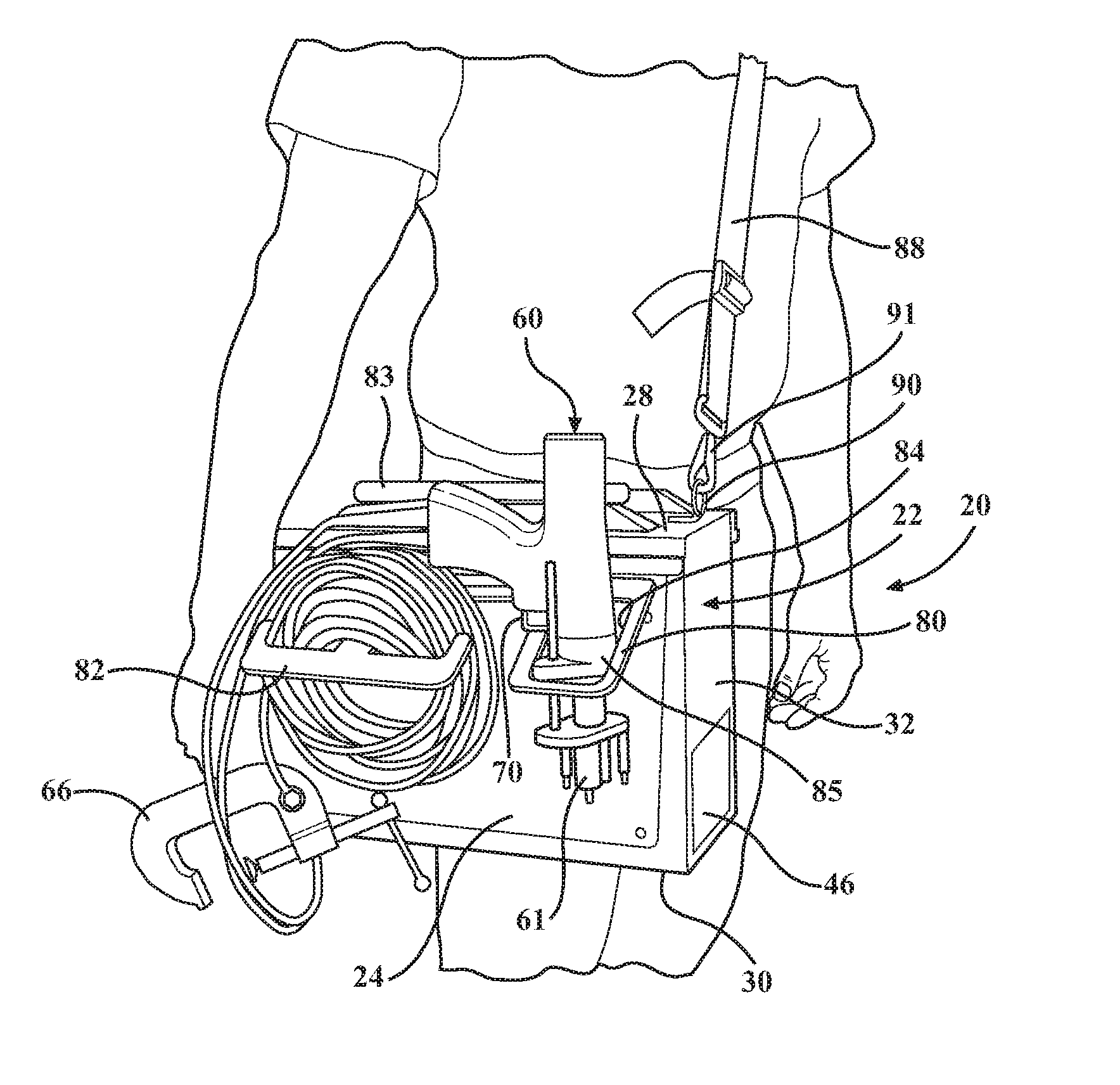
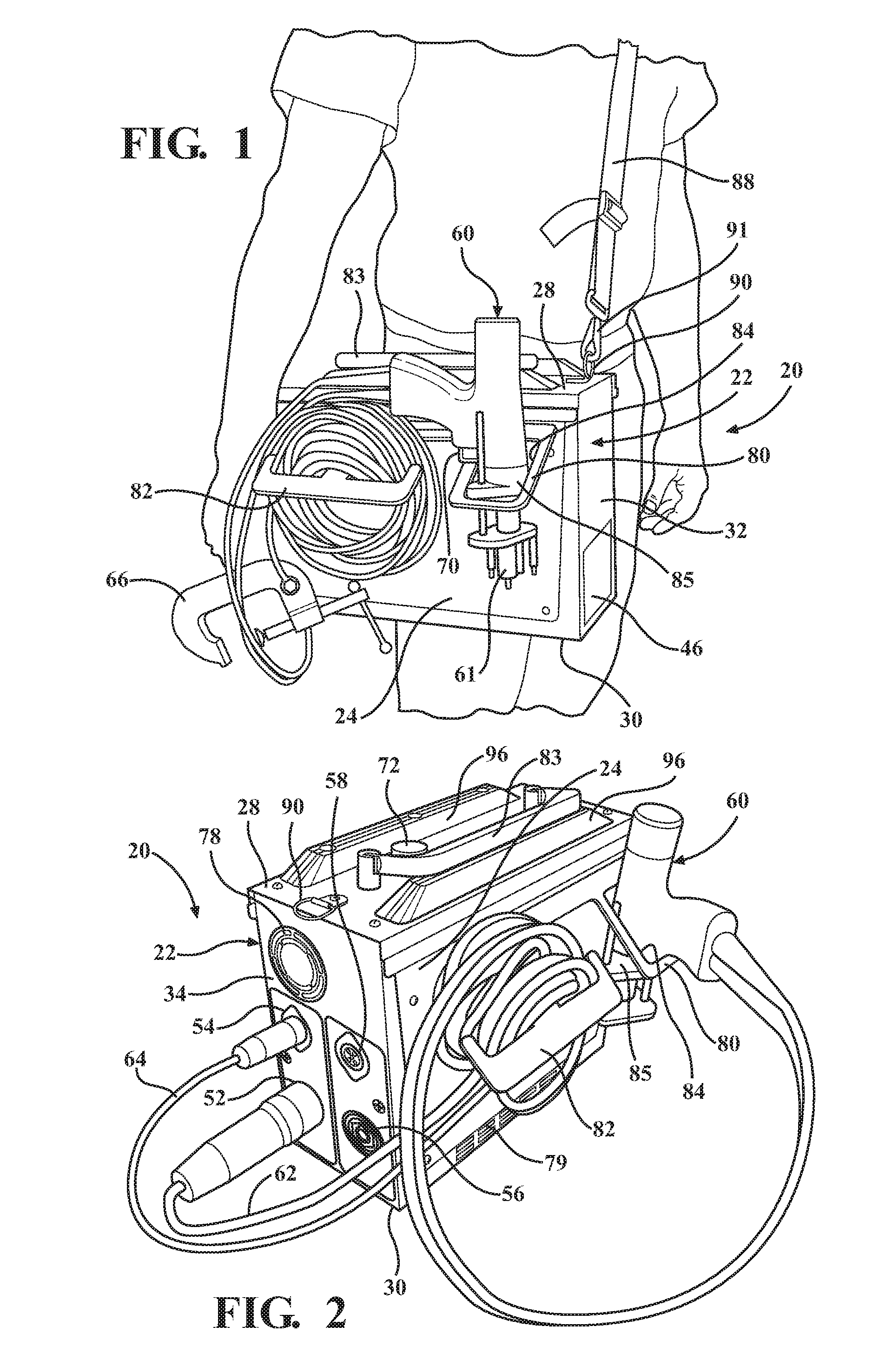
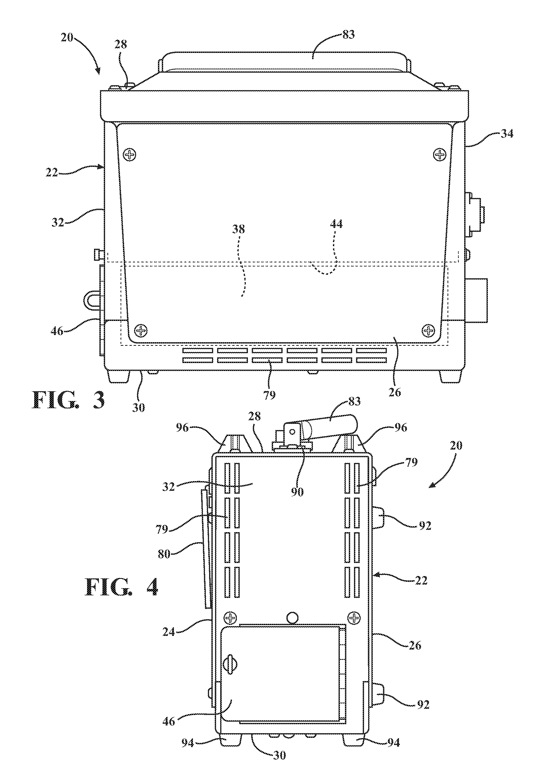
[0022]Capacitive discharge (CD) welders have historically been powered from AC power outlets, typically 115 VAC / 60 Hz in the United States, or 220 VAC / 50 Hz in Western Europe. Specifically, CD welders require substantial charging current to charge the capacitor bank rapidly between welds. Because of this requirement, traditional CD welders typically require 10-20 amp capacity from a 115 VAC line, or 5-10 amp capacity from a 220 VAC line. This requirement is met by having a high capacity line cord for power, usually a 16 AWG to 14 AWG, 3-conductor cord. This cord, when extended to allow the welder to be used at a distance from the power outlet, adds substantial weight, restricted movement, safety concerns (shock / tripping / arc flash) and limited portability to the CD welder. The portable stud welder apparatus 20 as disclosed herein eliminates the need for the line cord, while also preserving the benefit of being a very light weight, portable stud welder.

[0023]Referring to the Figures, ...


PUM

PropertyMeasurementUnit
weightaaaaaaaaaa
energyaaaaaaaaaa
angleaaaaaaaaaa

Abstract

A portable stud welder apparatus is provided for welding a stud onto a work piece. The portable stud welder apparatus includes a housing and an energy storage device. A weld stud gun that is configured to hold a weld stud is electrically connected to the energy storage device for receiving energy from the energy storage device to pass a current through the stud and the work piece to form a weldment. At least one battery of the lithium ion type that is removeably coupled to the housing to establish an electrical connection with said energy storage device and provide energy to the energy storage device.

Description

CROSS REFERENCE TO RELATED APPLICATION[0001]The present application claims priority to U.S. Provisional Patent Application Ser. No. 62 / 207,544, filed on Aug. 20, 2015, and entitled “LIGHT WEIGHT CORDLESS STUD WELDER”, the disclosure of which is hereby incorporated by reference as though set forth fully herein.BACKGROUND OF THE INVENTION[0002]1. Field of the Invention[0003]The present invention relates to a stud welder, and more particularly to a battery-powered, portable stud welder.[0004]2. Description of the Prior Art[0005]Stud welding is a technique for welding a fastener, such as stud or other fastener, to a base metal of a work piece. Various stud welder systems are known in the art for this purpose. One such type of stud welder system is known as a capacitive discharge (CD) system, which typically includes a charging circuit, an energy storage device, e.g., one or more capacitors, and a discharge circuit which extends through a weld stud gun. The power supply for such welding ...

Claims


Application Information

Patent Timeline
Patent Type & Authority Applications(United States)
IPC IPC(8): B23K9/20H02J7/00H01M2/10B23K9/10H01M10/0525
CPCB23K9/202B23K9/1006H01M2220/30H01M2/1022H02J7/0052H01M10/0525B23K11/0053B23K11/26B23K11/28Y02E60/10H02J7/00H01M50/20
Inventor SCHRAFF, SCOTT J.CHURCH, LARRY L.BROOKS, STEPHEN D.KRUPP, JEFFREY
Owner NELSON STUD WELDING
Why Eureka
Try Eureka