Aerodynamic control system for vehicles

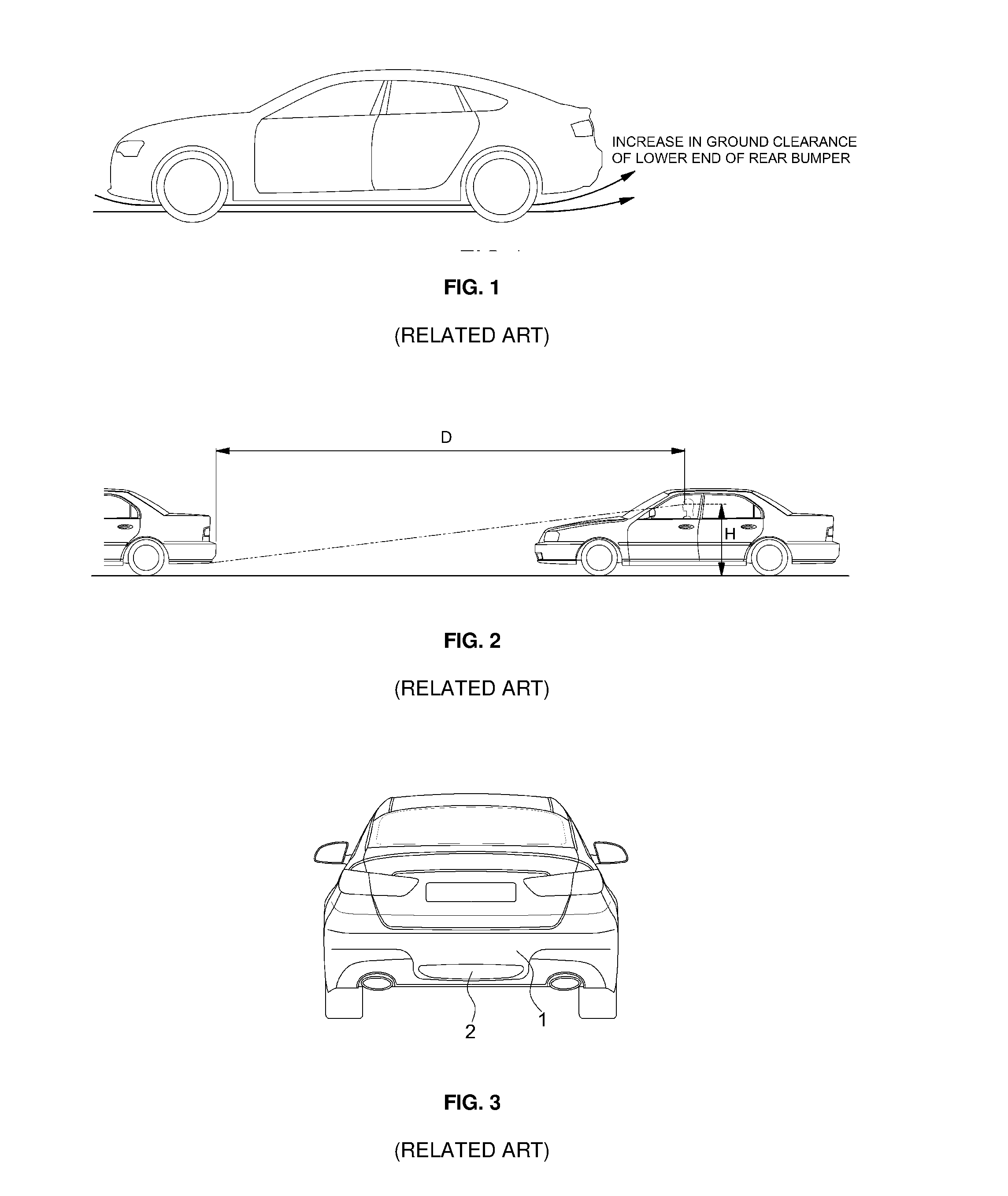
a control system and vehicle technology, applied in vehicle components, vehicle body streamlining, road transportation emission reduction, etc., can solve the problems of limited effect of aerodynamic performance generated by the hole b>2/b>, limited visibility of the lower end of the rear bumper, and inability to etc., to enhance fuel efficiency and driving stability of the vehicle, improve the aerodynamic performance of the vehicle, and increase the visible amount of the lower part of the vehicl

Active Publication Date: 2017-02-23
HYUNDAI MOTOR CO LTD
View PDF24 Cites 16 Cited by
  • Summary
  • Abstract
  • Description
  • Claims
  • Application Information

AI Technical Summary

Benefits of technology

[0017]The present invention provides an aerodynamic control system for vehicles which may improve aerodynamic performance of a vehicle, without increasing the visible amount of the lower part of the vehicle or limiting design of the vehicle, and can enhance fuel efficiency and driving stability of the vehicle.

Problems solved by technology

However, an increase in the ground clearance of the lower end of the rear bumper causes a large region of the lower part of the vehicle frame to be exposed from a rear position of the vehicle and is thus disadvantageous in terms of the exposure (visible amount) of the lower part of the vehicle.
Therefore, vehicle manufacturers set up a standard to minimize the visible amount of the lower part of a vehicle at a driver's eye height H of a rear vehicle, as exemplarily shown in FIG. 2 (RELATED ART), and an increase in the ground clearance of the lower end of the rear bumper is limited in improving aerodynamic performance of the vehicle due to increase in the visible amount of the lower part of the vehicle and design limitations.
However, since the hole 2 is always visible, application of the hole 2 is disadvantageous in terms of vehicle design, and the effect on aerodynamic performance generated by the hole 2 is minimal.
Further, in the case of a flap-type active rear diffuser, when a vehicle travels at a high speed, a flow diffusion angle may be controlled according to operation of a diffuser flap at the lower end of a rear bumper, but the diffuser flap moves based on the lower end surface of a conventional bumper, and thus an increase in the flow diffusion angle is restricted.

Method used


Image

  • Aerodynamic control system for vehicles
  • Aerodynamic control system for vehicles
  • Aerodynamic control system for vehicles

Examples


Embodiment Construction

[0031]Hereinafter reference will now be made in detail to various embodiments of the present invention, examples of which are illustrated in the accompanying drawings and described below. While the invention will be described in conjunction with exemplary embodiments, it will be understood that present description is not intended to limit the invention to those exemplary embodiments. On the contrary, the invention is intended to cover not only the exemplary embodiments, but also various alternatives, modifications, equivalents and other embodiments, which may be included within the spirit and scope of the invention as defined by the appended claims.

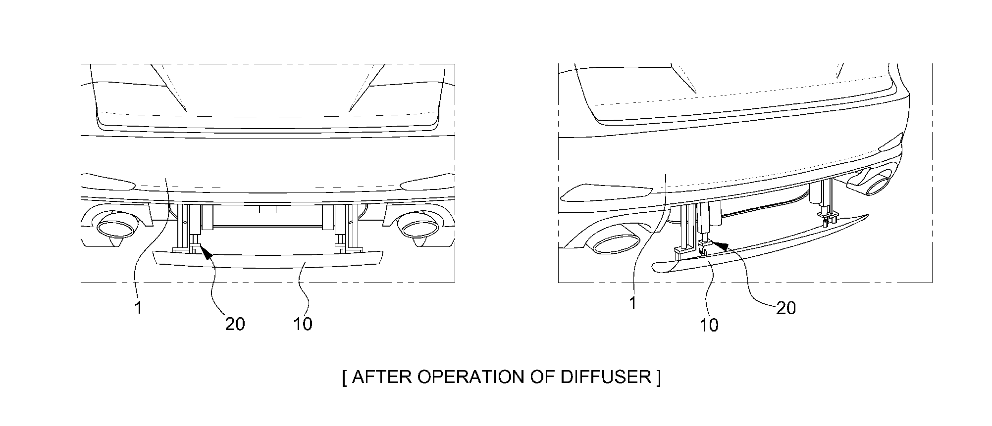
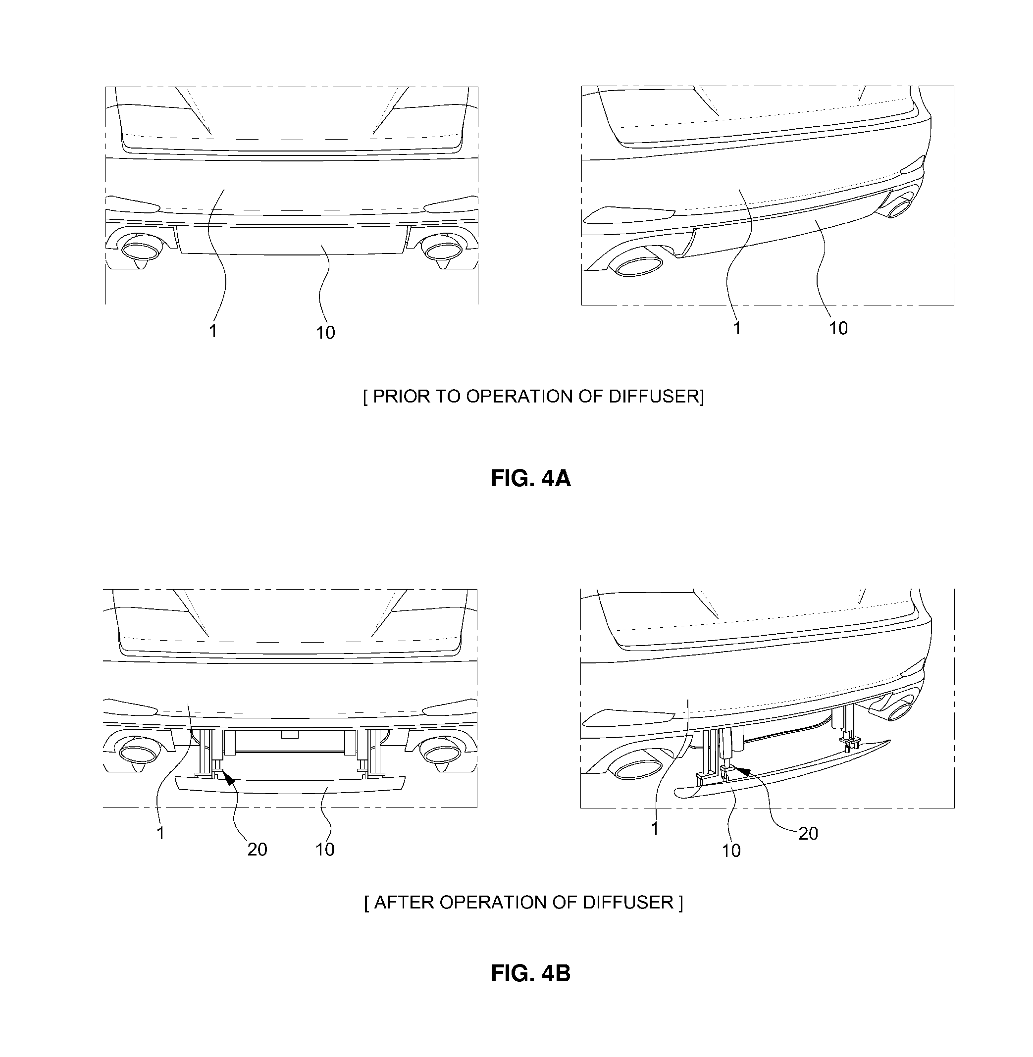
[0032]The present invention provides an aerodynamic control system for vehicles which may improve aerodynamic performance of a traveling vehicle and enhance fuel efficiency and driving stability of the vehicle.

[0033]For this purpose, the aerodynamic control system in accordance with the present invention includes a rear diffuser integrate...


PUM


Abstract

An aerodynamic control system for vehicles may improve aerodynamic performance of a vehicle and enhance fuel efficiency and driving stability of the vehicle. The aerodynamic control system includes a diffuser combined with a rear bumper at an ascending position so as to constitute part of a bumper surface of the rear bumper and separated from the rear bumper at a descending position so as to pass air exhausted from a lower part of the vehicle to a rear part of the vehicle along upper and lower surfaces of the diffuser, and a diffuser driving unit that connects a vehicle frame panel in a front of the rear bumper to the diffuser, supporting the diffuser on the vehicle frame panel, and adjusting upward and downward movement of the diffuser and the angle of the diffuser.

Description

CROSS-REFERENCE TO RELATED APPLICATION[0001]This application claims under 35 U.S.C. §119(a) the benefit of Korean Patent Application No. 10-2015-0117057 filed on Aug. 20, 2015, the entire contents of which are incorporated herein by reference.BACKGROUND[0002](a) Technical Field[0003]The present invention relates to an aerodynamic control system for vehicles, more particularly, to an aerodynamic control system for vehicles which may improve aerodynamic performance of a traveling vehicle and increase fuel efficiency and driving stability of the vehicle.[0004](b) Description of the Related Art[0005]As is generally known, when a vehicle is in motion, a front part of a vehicle frame pushes air in the upward, downward, leftward and rightward directions, and the pushed air moves to the rear part of the vehicle frame and returns to its original position.[0006]It takes a period of time for such air to return to its original position and, as the time increases, a vacuum region formed at a rea...

Claims


Application Information

Patent Timeline
Patent Type & Authority Applications(United States)
IPC IPC(8): B62D35/00B62D35/02
CPCB62D35/02B62D35/007Y02T10/82Y02T10/88
Inventor KIM, HAK LIM
Owner HYUNDAI MOTOR CO LTD
Why Eureka
Try Eureka