Lateral Flow Diagnostic Devices with Integrated Electronic Components and Methods of Use Thereof

a technology of electronic components and diagnostic devices, applied in measurement devices, scientific instruments, instruments, etc., can solve problems such as limited wide-spread use, difficult test performance protocols, and compromise and user-dependent test accuracy and reproducibility

Inactive Publication Date: 2017-03-09
TAMIR IDAN
View PDF1 Cites 17 Cited by
  • Summary
  • Abstract
  • Description
  • Claims
  • Application Information

AI Technical Summary

Benefits of technology

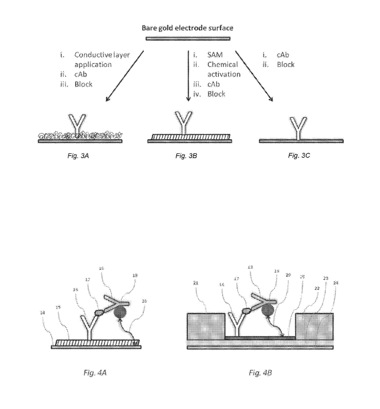
[0032]In some embodiments, the external, clean surface of the electrodes of the device of the present invention is modified by various chemical reagents and techniques known in the art to fabricate chemically-reactive end groups—such as: maleimide, epoxy, and N-hydroxysuccinimide (NETS) ester—on such electrode surfaces. In some preferred embodiments, where the electrode's surface material is gold, the nascent electrode surface produced following surface cleaning is protected from undesired subsequent adsorption of contaminating chemical species by forming a densely-packed self-assembled monolayer (SAM) on its surface immediately following surface cleaning. Examples of appropriate SAM-forming substances are, but not limited to, organic sulfur-containing compounds that avidly bind to the gold surface via their sulfur atoms, such as: organic thiols, sulfides, thioesters and disulfides.
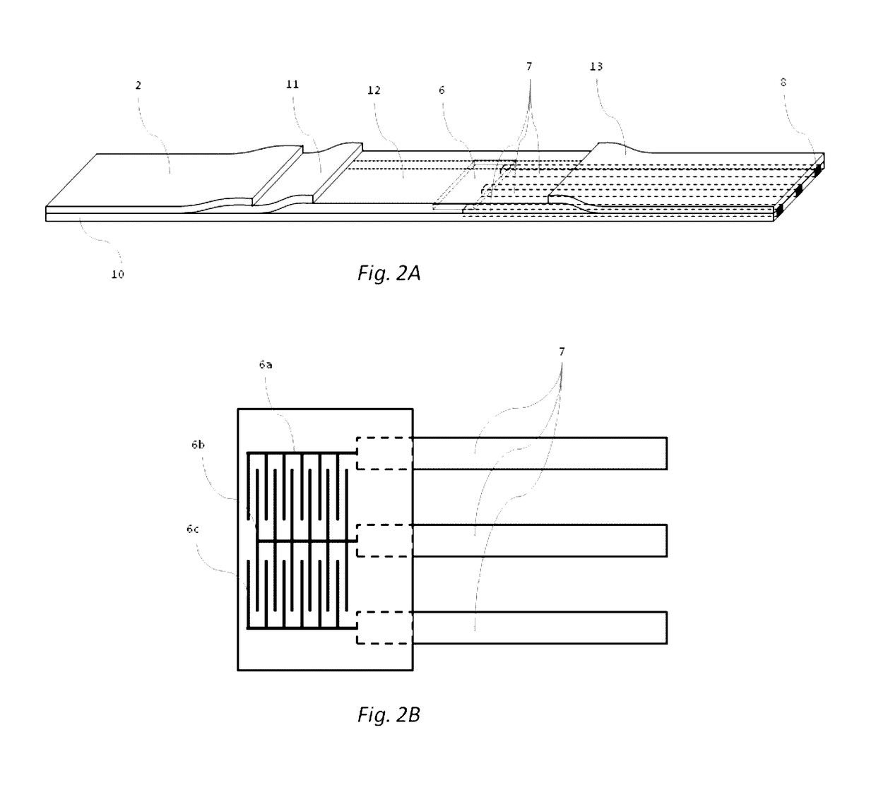
[0033]In some embodiments, the chemically-reactive end groups that are generated on the external surface of the biosensor electrode of the present invention are further reacted with an analyte-specific capture reagent, thereby covalently immobilizing such capture reagent to the electrode's external surface. Alternatively, the analyte-specific capture reagent may be directly immobilized to the biosensor surface through non-specific interactions, and / or specific linkers that are attached to the capture reagent and are reactive with the biosensor electrode's surface. An example for such specific linkers are bi-functional amine-reactive (e.g., NHS ester) organic molecules that incorporate a thiol functionality reactive with the gold electrode surface. Analyte binding to such electrode surface-immobilized capture reagent can be monitored by measuring the time-dependent electrochemical impedance signal (Z) between adjacent electrode pairs (working vs. reference electrode—Zwr). In some embodiments of the present invention, Zwr is compared with an equivalent signal—Zcr—measured between a control electrode, carrying a reagent that is a close analog of the capture reagent but non-specific to the analyte (e.g., host species- and isotype-matched antibody), and the reference electrode. Both Zwr and Zcr signals emanate from electrode pairs that are positioned to equivalently interact with the analyte solution—i.e., they occupy equivalent positions with respect to fluid flow along the LFT membrane. Real-time difference between these two signals in terms of their phase and intensity (ΔZ(t)=Zwr(t)−Zcr(t) is then taken to represent the specific, time-dependent binding of the analyte to its capture reagent on the working electrode. Measurement of the time-dependent differential electrochemical impedance signal (ΔZ(t)) helps in minimizing non-specific contributions to the electrode's impedance from temporal and spatial variations in buffer composition, temperature, pH and biochemical composition of the tested sample.

Problems solved by technology

Although these lateral flow tests (LFTs) have many advantages, such as being based on a mature technology that enjoys wide user acceptance and recognition, clear development & regulatory paths, established manufacturing processes, and is both cost-effective and scalable, they have several disadvantages that limit their wide-spread use, especially for self-testing.
These disadvantages include, among other: challenging test performance protocols, especially in the hands of untrained individuals; compromised and user-dependent test accuracy and reproducibility; ambiguity in test results detection—LFTs are mostly qualitative in nature and depend on visual signal detection for their interpretation; problematic results interpretation and correlation—consumers are often confused about what to do with RDT results and how these would correlate with test results obtained at the POC or hospital lab.
Additionally, results traceability and their communication to the healthcare professional are challenging with current RDTs.
Although these LOC devices provide accurate diagnostic test results for multiple analytes in a relatively short period of time, their cost and the significant user expertise required for their proper operation has generally rendered them unsuitable for testing outside the POC.
Amperometric biosensors generally rely on electrochemical reactions mediated by specific enzymes (e.g., glucose oxidase) for analyte detection and quantification, and are less optimal for detecting and quantifying binding events at the biosensor surface.
However, non-specific interactions between the channel's surface material and the myriad of biochemical entities present in biological samples may overwhelm specific interactions with the analyte of choice, limiting FETs signal-to-noise ratio (S / N) and rendering them sub-optimal for clinical diagnostic applications.
In order to minimize such non-specific interactions, potentiometric biosensor-based POC devices (e.g., iSTAT by Abbott) rely on elaborate and relatively expensive microfluidic technologies, limiting their application to professional, LOC-based systems.
Although EIS has been extensively investigated in the laboratory, it has so far gained limited utilization in POC diagnostic applications and products, putatively due to its intrinsic low signal-to-noise ratio (S / N) in detecting analytes in biological samples, combined with requirement for sophisticated and expensive instrumentation for signal detection and analysis.
Taken together, the above limitations have until now restricted the use of the different electronic sensing technologies in diagnostic applications where target recognition is achieved by detecting its specific interaction with an immobilized capture reagent.
Furthermore, implementing these different electronic sensing modalities within the framework of disposable lateral flow tests raises additional cost and performance issues that have until now hampered the adoption of such diagnostic devices.
One of the main issues to address when attempting the utilization of these and other biosensor technologies is their S / N, which typically limits their analyte cutoff value (also known as limit of detection (LOD)) to the nM range.
It is important to note that the above-mentioned approaches for LOD improvement had, as of yet, limited impact on the wide-spread adoption of such devices, with the exception of the mentioned iSTAT amperometric technology.

Method used


Image

  • Lateral Flow Diagnostic Devices with Integrated Electronic Components and Methods of Use Thereof
  • Lateral Flow Diagnostic Devices with Integrated Electronic Components and Methods of Use Thereof
  • Lateral Flow Diagnostic Devices with Integrated Electronic Components and Methods of Use Thereof

Examples


Embodiment Construction

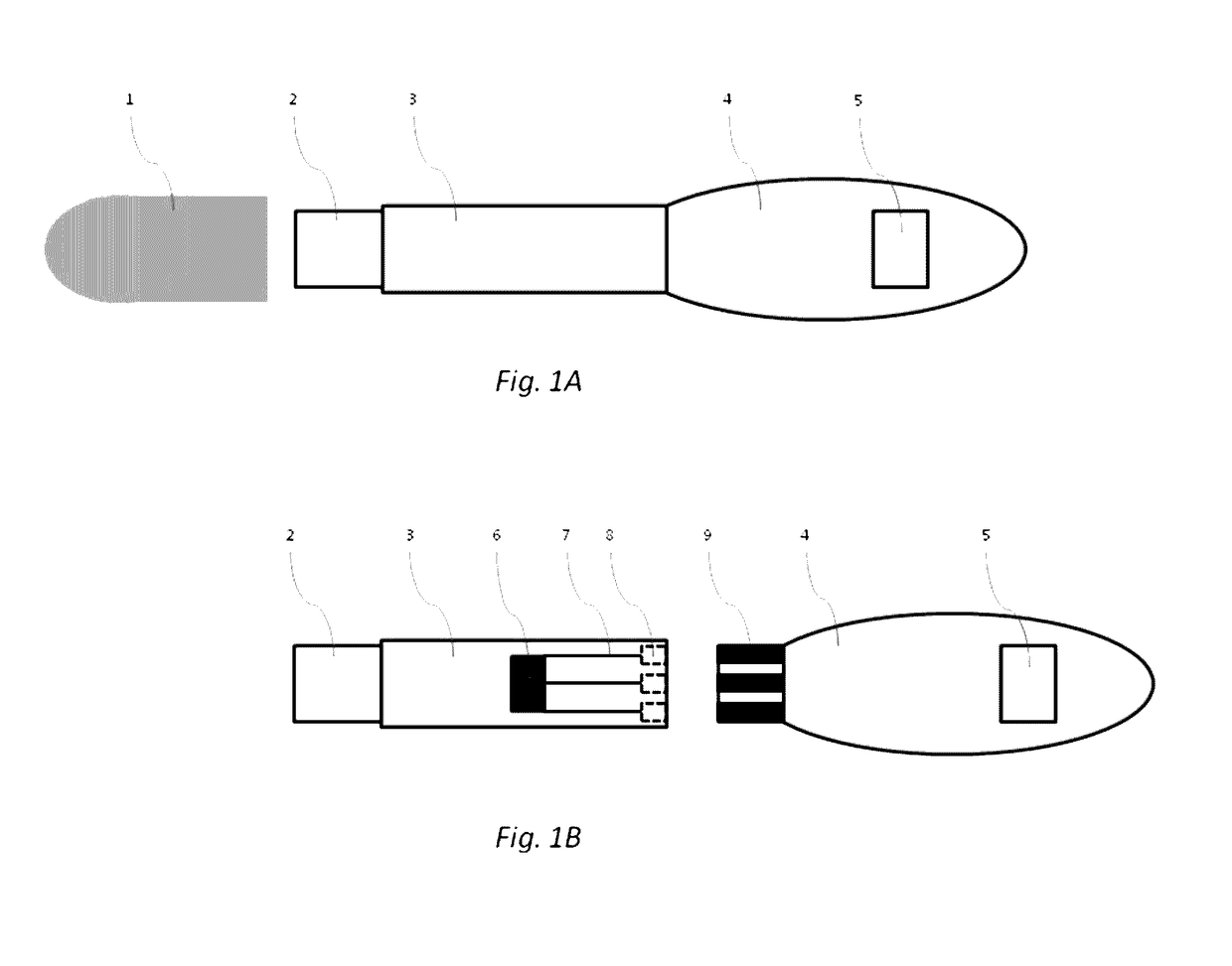
[0042]In some embodiments, the device of the present invention is configured to permit conducting an immunoassay for a specific analyte or set of analytes that are extracted from a biological sample or present in a biological fluid, such as blood, urine, saliva etc. In some embodiments, the device of the present invention integrates traditional lateral flow immunochromatographic assay technologies with those of electronic biosensors in a single apparatus, employing electroactive labels that act to amplify the change in impedance signal at a biosensor surface following detection reagent immobilization. Additionally, proper selection and construction of the electroactive label relative to the biosensor surface prevents non-specific contact between the two, promoting such interaction only upon the specific contact between the detection reagent, the analyte and the capture reagent. Such integration is expected to reduce the complexity of diagnostic test performance, while increasing tes...


PUM

PropertyMeasurementUnit
heightaaaaaaaaaa
pore sizesaaaaaaaaaa
frequenciesaaaaaaaaaa

Abstract

A biological sample device for detecting the presence or absence of specific analytes in a sample is provided. A sample, such as a blood or urine sample or a pre-processed tissue sample is collected on a porous pad. A first membrane in liquid communication with the sample pad includes an analyte-specific, electroactively-labeled detection reagent reactive with the an analyte. A second membrane in liquid communication with the first membrane includes a biosensor whose surface has been modified by an analyte-specific capture reagent. The analyte-binding capture reagent immobilizes the analyte electroactive label complex on the surface of the biosensor, whereby direct interaction of the electroactive label with the surface of the biosensor generates an electric signal used by an electronic processing unit to determine whether the analyte is present in the sample.

Description

[0001]This application claims priority under 35 U.S.C. §119(e) to U.S. provisional application Ser. No. 62 / 214,048, filed Sep. 3, 2015, the entire disclosure of which is incorporated by this reference into the present U.S. patent application.BACKGROUND AND SUMMARY OF THE INVENTION[0002]The present invention will be further explained with reference to the attached drawings, wherein like structures are referred to by like numerals throughout the several views. The drawings shown are not necessarily to scale, with emphasis instead generally being placed upon illustrating the principles of the present invention. Further, some features may be exaggerated to show details of particular components.[0003]The figures constitute a part of this specification and include illustrative embodiments of the present invention and illustrate various objects and features thereof. Further, the figures are not necessarily to scale, some features may be exaggerated to show details of particular components....

Claims


Application Information

Patent Timeline
Patent Type & Authority Applications(United States)
IPC IPC(8): G01N33/543G01N27/414G01N27/327
CPCG01N33/54373G01N27/4145G01N27/3275G01N33/5438G01N33/558G01N33/54388
Inventor TAMIR, IDAN
Owner TAMIR IDAN
Why Eureka
Try Eureka