Optical signal transmission apparatus and optical signal transmission method
a technology of optical signal and transmission apparatus, applied in the field of optical communication technology, can solve the problems of difficult to correctly detect a received bit, difficult to detect the above-described short preamble signal and long preamble signal at the receiving end, etc., and achieve the effect of reducing the optical fiber transmission path
- Summary
- Abstract
- Description
- Claims
- Application Information
AI Technical Summary
Benefits of technology
Problems solved by technology
Method used
Image
Examples
first embodiment
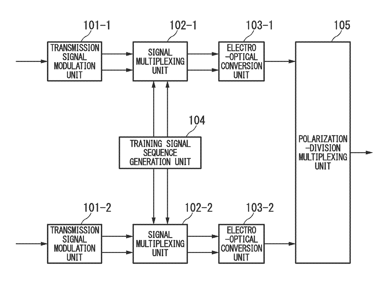
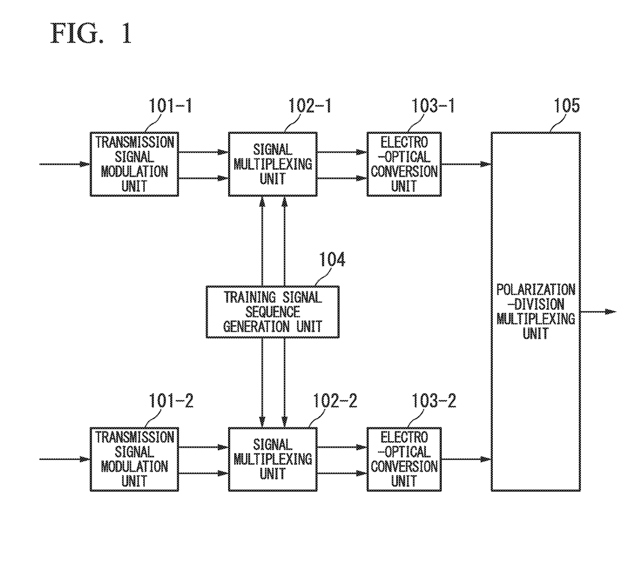
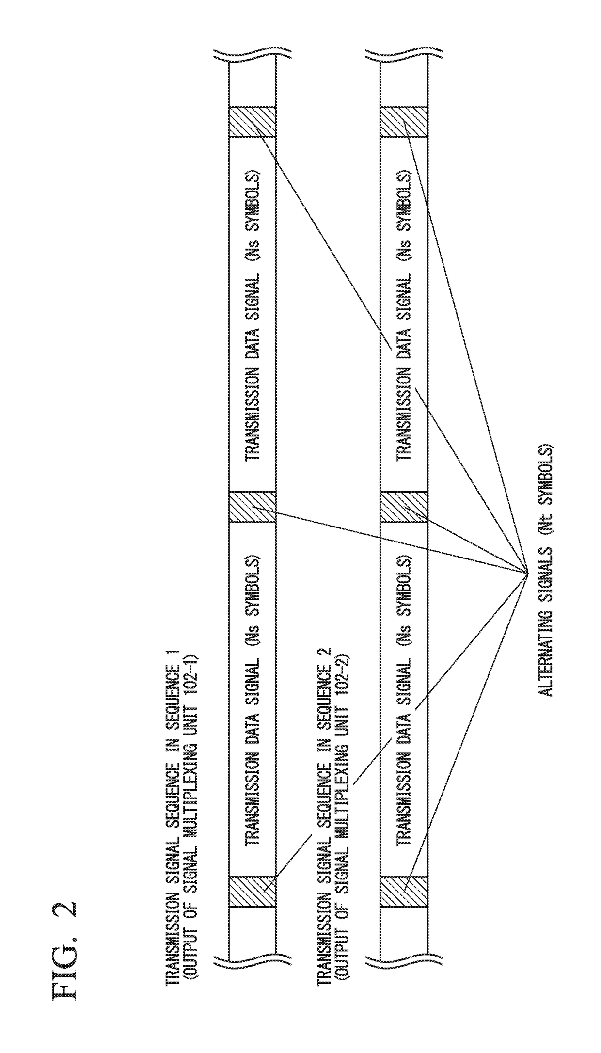
[0069]FIG. 1 is a block diagram illustrating a configuration example of an optical signal transmission apparatus in the first embodiment of the present invention. In FIGS. 1, 101-1 and 101-2 denote transmission signal modulation units, 102-1 and 102-2 denote signal multiplexing units, 103-1 and 103-2 denote electro-optical conversion units, 104 denotes a training signal sequence generation unit, and 105 denotes a polarization-division multiplexing unit. The optical signal transmission apparatus includes the transmission signal modulation units 101-1 and 101-2, the signal multiplexing units 102-1 and 102-2, the electro-optical conversion units 103-1 and 103-2, the training signal sequence generation unit 104, and the polarization-division multiplexing unit 105. It is to be noted that an example of polarization-division multiplexing transmission using two orthogonal polarizations (X polarization and Y polarization) will be described as follows, but such a configuration may not be nece...
second embodiment
[0089]Next, the second embodiment of the present invention will be described. FIG. 4 is a block diagram illustrating a configuration example of an optical signal transmission apparatus in the second embodiment of the present invention. The second embodiment of the present invention is different from the first embodiment of the present invention in that the training signal sequence generation unit 104 is used as a training signal mapping unit 201. The training signal mapping unit 201 performs symbol mapping on the training signal using the same modulation scheme as that of the transmission signal and generates a training signal sequence.
[0090]The present embodiment uses a method for reducing a correlation between the X-polarization and the Y-polarization by using sequence patterns that are orthogonal in the X-polarization and the Y-polarization. That is, in the present embodiment, the training signal mapping unit 201 determines a pattern phase and a low cycle pattern so that a mutual...
third embodiment
[0100]Next, the third embodiment of the present invention will be described. The third embodiment is different from the first and second embodiments in that the modulation sequence generation units 1003-1 to 1003-4 perform modulation so that power of a training signal sequence is reduced without spreading the spectrum of the training signal sequence. Because the cross-phase modulation effect is proportional to instantaneous power as described above, it is possible to suppress the deterioration of an error rate caused by cross-phase modulation by reducing the amplitude of the training signal sequence.
[0101]FIG. 14 illustrates an example of a frequency spectrum in the basic symbol mapping of the training signal sequence in the third embodiment. FIG. 14 is an example of a frequency spectrum of the training signal sequence in 8 QAM and 16 QAM. In this case, the X-polarization and the Y-polarization have the same complex amplitude. When one cycle is defined as four symbols, a basic train...
PUM
 Abstract
Description
Claims
Application Information
 - R&D
- Intellectual Property
- Life Sciences
- Materials
- Tech Scout
- Unparalleled Data Quality
- Higher Quality Content
- 60% Fewer Hallucinations
Browse by: Latest US Patents, China's latest patents, Technical Efficacy Thesaurus, Application Domain, Technology Topic, Popular Technical Reports.
© 2025 PatSnap. All rights reserved.Legal|Privacy policy|Modern Slavery Act Transparency Statement|Sitemap|About US| Contact US: help@patsnap.com


