Systems and Methods for Enclosing Instrument Encasing Systems

a technology of instrument encasing and system, which is applied in the direction of measuring apparatus housings, measuring apparatus for damping movement parts, etc., can solve the problems of affecting the overall weight and stability of the mounted housing, and affecting the operation of the instrument. , to achieve the effect of easy mounting and/or disassembly of instruments, and increased overall weight and stability

Inactive Publication Date: 2017-03-16
PHOENIX INTL MARKETING LLC
View PDF4 Cites 6 Cited by
  • Summary
  • Abstract
  • Description
  • Claims
  • Application Information

AI Technical Summary

Benefits of technology

[0015]In one aspect, an improved instrument encasing system may solve a variety of problems associated with existing systems. The improved instrument encasing system may include a suspension bracket and back plate that enable tool-less mounting and/or disassembly. The system suspension bracket also may provide a template for easy alignment and selection of a mounting position. The back plate may have a variable geometry, such as a temporarily reduced diameter, to enable screw-less and/or glue-less and/or other assisted assembly, and also enable quick and easy access for service or repair to instr...

Problems solved by technology

For example, when instruments are deployed into moving platforms such as ships, yachts, power boats, mobile homes and the like, it is essential they be mounted securely and not left to swing on the single suspension point normally provided for in devices intended only for static deployment as the movement of the vehicle may cause the instrument to easily dislodge or fall and be damaged and/or be rendered inoperable.
But the rear flange has not been without its disadvantages particularly in their current evolution.
When flange screw mounted to a wall or bulkhead, removal requires the use of tools and any mishap such as a screwdriver escaping from the control of the screw slot will damage the surrounding case and wall areas.
In addition, repeated removal and replacement results in screw holes gradually enlarging, thus rendering the mounting weak and eventually requiring a new position to be selected, which results in surface disfigurement.
However, these systems are expensive to manufacture.
These systems generally fail to provide adequate ventilation of the instrument casing and also make it difficult to access to the instrument housed therein.
It also is difficult to mark out a location for fixation of encasement system.
This can be an arduous and inaccurate process if not performed correctly and risks resulting in a misaligned attachment quite simply because one cannot simultaneously be close to support the ...

Method used


Image

  • Systems and Methods for Enclosing Instrument Encasing Systems
  • Systems and Methods for Enclosing Instrument Encasing Systems
  • Systems and Methods for Enclosing Instrument Encasing Systems

Examples


Embodiment Construction

[0039]The elements illustrated in the Figures interoperate as explained in more detail below. Before setting forth the detailed explanation, however, it is noted that all of the discussion below, regardless of the particular implementation being described, is exemplary in nature, rather than limiting.

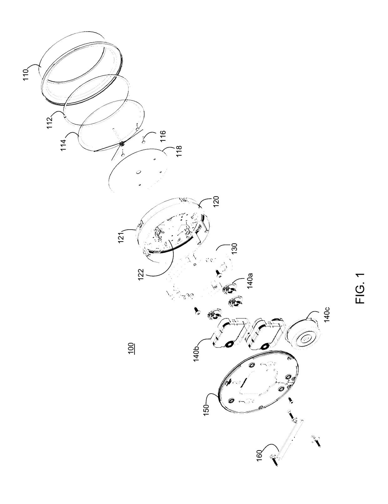
[0040]Referring to the drawings, and initially to FIG. 1, an exploded view exemplary instrument encasing system 100 is shown. In the illustrated embodiment, the instrument casing system 100 may include an outer housing or casing 110 that contains an inner housing 120 and gauge mount plate 122 that may include one or more calibrated dials, gauges and the like 140a-c; a front lens 114; a lens compression support thread 112; a dial 118; indicating hands 116; one or more stabilization weights 130; a back plate 150, and a suspension bracket 160. The system may include more or less components.

[0041]The outer housing 110 may provide an exterior shell that houses the other components of the enc...


PUM


Abstract

Improved instrument encasing systems may solve a variety of problems associated with existing systems. In one aspect, an improved instrument encasing system may include a suspension bracket and back plate that enable tool-less mounting and/or disassembly and/or security in mobile installations. Optionally, the system suspension bracket also may provide a template for easy alignment and selection of a mounting position and/or installation thereto. In some embodiments, the back plate may be temporarily reduced in diameter to enable quick and easy access to instruments mounted on an inner housing, or for access to the dial face for personalization. In another aspect, an inner housing of the instrument encasing system may provide one or more spring blades that receive instrument mounting sub-assemblies that provide for easy mounting and replacement of instruments. Optionally, stabilization weights also may be provided in the inner housing to absorb vibrations and increase the overall weight and stability of the housing, enabling lighter materials to be used in the manufacture of other components. In some embodiments, a Physical Vapor Deposition coating may be applied to an outer housing to provide various functional and/or aesthetic qualities.

Description

RELATED APPLICATIONS[0001]The present is related to a non-provisional patent application entitled “Instrument Encasing Systems” bearing Ser. No. 14 / 855,691 filed on the same date as the present application, the disclosure of which is hereby incorporated herein by reference. This related application is owned by the assignee of this present application.BACKGROUND OF THE INVENTION[0002]1. Technical Field[0003]The present invention relates generally to the field of analogue gauge and accessory encasements, and more particularly, to instruments for mobile deployment in harsh outdoor marine, recreational, and horticultural locations as well as static industrial, domestic, and commercial usage sectors.[0004]2. Related Art[0005]Many gauge instruments such as clocks, weather instruments, speed logs, inclinometers and like used in, for example, the mobile sectors described above, are typically mounted to a wall, bulkhead or other appropriate surface in a variety of methods all of which have s...

Claims


Application Information

Patent Timeline
IPC IPC(8): G01D11/10G01D11/24
CPCG01D11/24G01D11/10
Inventor BAIRD, KEVINBOWEN, BARRIE H.
Owner PHOENIX INTL MARKETING LLC
Why Eureka
Try Eureka