High isolation power combiner/splitter and coupler

a technology of combiner/splitter and high isolation power, which is applied in the direction of electrical equipment, multiple-port networks, coupling devices, etc., can solve the problems of increased insertion loss, drawback of requiring additional circuit size, and the relatively large size of multi-section power combiner cannot be tolerated

Active Publication Date: 2017-03-16
THORUP KARL L
View PDF0 Cites 32 Cited by
  • Summary
  • Abstract
  • Description
  • Claims
  • Application Information

AI Technical Summary

Problems solved by technology

While this design offered a better solution to many systems, this approach has the drawback of requiring additional circuit size due to additional transmission line sections.
It also suffers from increased insertion loss, since the signal must travel through longer transmission lines.
For many circuits, the relatively large size of a multisection power combiner cannot be tolerated.
Additional insertion loss as well, is almost always a drawback in power combiners.
However, to date there has been little improvement on increasing the magnitude of the in-band isolation between uncommon ports.
While this improves the out-of-band port to port isolation, the in-band isolation is not significantly improved.
This design also suffers from increased insertion loss over a typical power combiner / splitter due to the signal going through a band pass filter as well as the combiner / splitter circuit.
These products, however, are relatively costly and exhibit non-linear characteristics at high input signal levels.
They also increase the signal path insertion loss.
Furthermore, they are not reciprocal circuits, and cannot be used as splitters without re-orienting the circulators or isolators.

Method used


Image

  • High isolation power combiner/splitter and coupler
  • High isolation power combiner/splitter and coupler
  • High isolation power combiner/splitter and coupler

Examples


Embodiment Construction

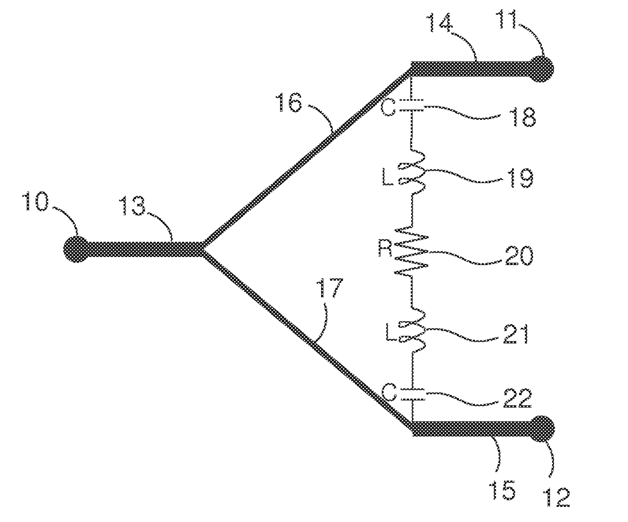
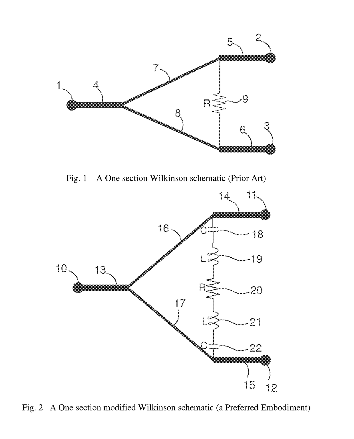
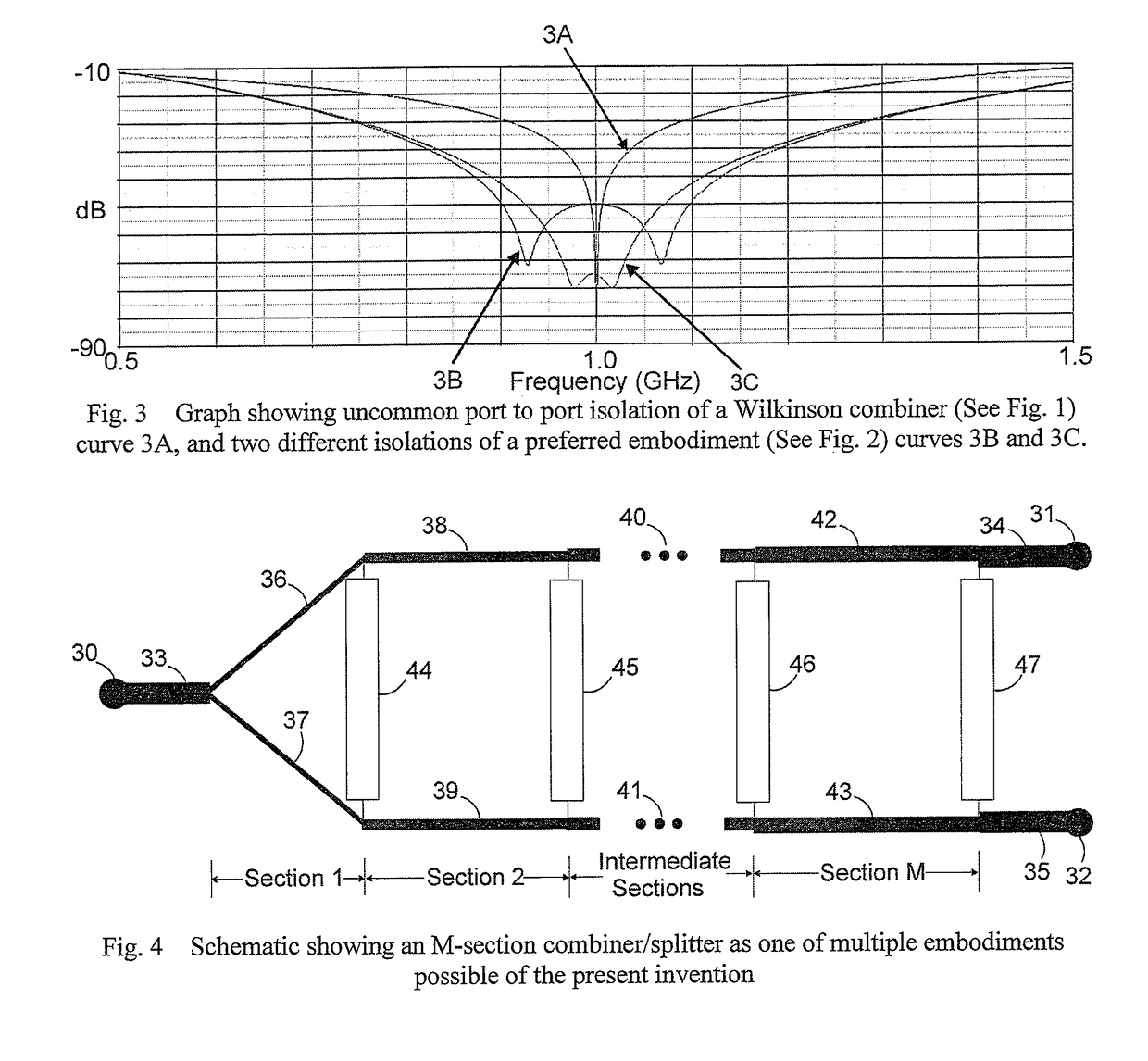
[0049]For purposes of this disclosure, the transmission line schematic symbols throughout all the figures represent both the signal carrying conductor and the return path or ground path conductor, such as is consistent for coaxial cable, coplanar, stripline or microstripline transmission lines or other transmission line structures. Additionally, the schematic elements portrayed as capacitances, inductances and resistances may be considered to be lumped elements, and may be elements etched on a circuit board or may be separate parts connected to the circuit board, or some other construction, such as integrated circuit implementations.

[0050]For purposes of this disclosure “coupling” and “coupler” may refer to any circuit providing at least one path between a port and one or more other ports either through a conductor, magnetic coupling, or electric field coupling or some combination of the three.

[0051]For purposes of this disclosure an electrical isolation provided over a “greater” ba...


PUM


Abstract

A power combiner has at least two uncommon ports and at least one common port. Isolation between the uncommon ports over a broad band is achieved through a lossy band response circuit having a phase and amplitude response effective to compensate for changes in phase and amplitude between the uncommon ports with change in frequency of an input signal. The lossy band response circuit may have a resistance approximating a resistance effective to isolate the uncommon ports over a bandwidth at a center frequency. A coupler may likewise increase the band for which an input port is isolated from the isolated port by coupling a lossy circuit between the input port and isolated port. The lossy circuit may be embodied as a lossy band response circuit.

Description

BACKGROUND[0001]Field of Invention[0002]This invention relates to high isolation power combiners / splitters and couplers, specifically to such combiners / splitters and couplers that are used in RF and microwave circuits.[0003]Description of Prior Art[0004]Special circuits are sometimes required to combine two or more high frequency RF or microwave signals. A commonly used circuit that can accomplish this is called a power combiner. An N-way combiner has one common port and N uncommon ports. The ports are places in the circuit that allow intentional connection to other external circuits. In general, a good power combiner should sum N input signals together with minimal signal energy or power loss. It should also keep the signals that are being summed together isolated from each other at the uncommon inputs. High uncommon port to uncommon port isolation can help to avoid impedance mismatches and signal degradation, and helps to minimize stress to circuitry connected to the uncommon port...

Claims


Application Information

Patent Timeline
Patent Type & Authority Applications(United States)
IPC IPC(8): H01P5/12
CPCH03H7/0123H03H7/09H03H7/48
Inventor THORUP, KARL L.
Owner THORUP KARL L
Why Eureka
Try Eureka