Frame assembly, stencil, screen printing device and screen printing method

a technology of screen printing and frame, applied in the field of display technology, can solve the problems of large amount of ink waste, damage to black, degrade the appearance of a product, etc., and achieve the effect of eliminating a segment difference, reducing the amount of mesh fabric material, and reducing the area of the mesh fabri

Active Publication Date: 2017-03-23
BOE TECH GRP CO LTD +1
View PDF15 Cites 0 Cited by
  • Summary
  • Abstract
  • Description
  • Claims
  • Application Information

AI Technical Summary

Benefits of technology

[0019]In a case where screen printing is performed by the screen printing device according to the present invention, since the second frame is provided to surround the first frame and the mesh fabric is provided between the first frame and the second frame, an area of the mesh fabric can be reduced. When the screen printing device according to the present invention is in use, ink only needs to be coated onto a portion of the mesh fabric which is located between the first frame and the second frame, and it only needs to drive the scraper to move a lap on the mesh fabric between the first frame and the second frame to cause the ink in the ink permeable area to be printed onto a blank margin of a touch panel. In the present invention, the mesh fabric needs not to be provided inside the first frame, thus an amount of material of the mesh fabric is reduced; in addition, the first frame has a hollow structure and will not bring contamination to the visible area of a touch panel, thus a protection film for protecting the visible area can be omitted, thereby eliminating a segment difference resulted from the protection film, and eliminating a risk that the scraper easily damages the mesh fabric. Furthermore, since an inner side and an outer side of the mesh fabric are fixed to the first frame and the second frame, respectively, forces applied to the mesh fabric are more uniform. As a result, when the scraper scrapes the mesh fabric, the scraped ink has a uniform thickness, and the quality of screen printing and a utilization ratio of the ink are increased. The screen printing device according to the present invention is applicable to performing screen printing on a touch panel.

Problems solved by technology

The secondary screen printing needs to be performed, because micro-cracks and notches will occur at an edge of each of the touch panels during the cutting and the edge grinding, damage the black matrix 2, and degrade the appearance of a product.
Thus, the large amount of ink is wasted, and the larger a size of the touch panel is, the lower a utilization ratio of the ink for screen printing is.
Although the protection film is very thin, it results in a non-negligible segment difference (i.e., unevenness of a surface).
In a severe case, “ink accumulation” and “ink overflow” may occur, and there is a risk that the scraper 44 may easily damage the mesh fabric 42.

Method used


Image

  • Frame assembly, stencil, screen printing device and screen printing method
  • Frame assembly, stencil, screen printing device and screen printing method
  • Frame assembly, stencil, screen printing device and screen printing method

Examples


first embodiment

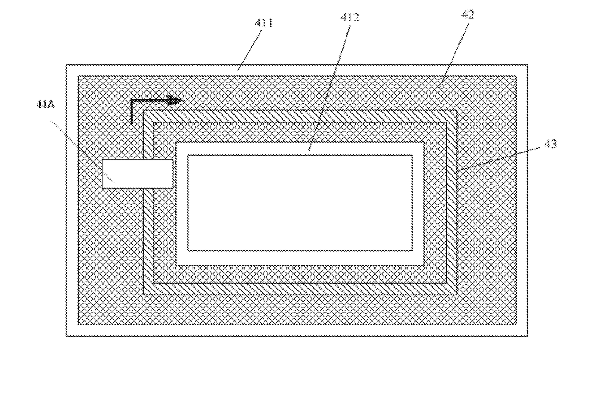
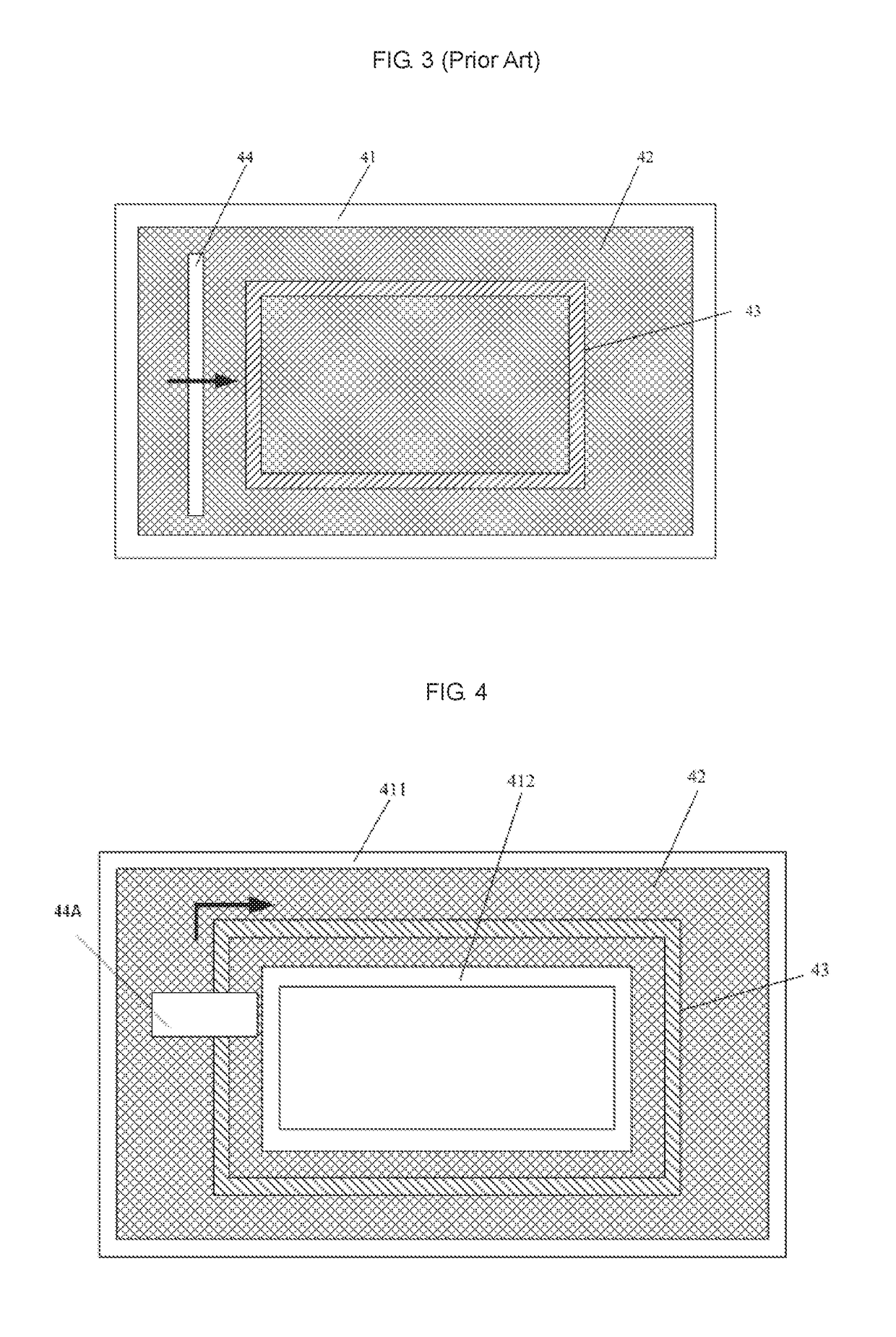
[0027]The present embodiment provides a frame assembly. As shown in FIG. 4, the frame assembly includes a first frame 412 and a second frame 411 provided to surround the first frame 412. The first frame 412 and the second frame 411 are configured to support mesh fabric 42 therebetween.

[0028]That is, a frame 41 in the prior art is in a shape of “Li”. However, the frame assembly according to the present embodiment includes the first frame 412 and the second frame 411 provided to surround the first frame 412, and thus is in a shape of “”. After mesh fabric 42 is provided between these two frames of the frame assembly, an inner side and an outer side of the mesh fabric 42 are fixed to the inner and outer frames (i.e., the first frame 412 and the second frame 411), respectively, thus the forces applied to the mesh fabric 42 are more uniform.

second embodiment

[0029]The present embodiment provides a stencil, which includes the frame assembly according to the first embodiment and the mesh fabric 42 provided between the first frame 412 and the second frame 411, wherein, at least a part of the mesh fabric 42 is an ink permeable area 43.

[0030]That is, in a screen printing device in the prior art, a scraper 44 moves horizontally, as shown by the arrow in FIG. 3. In the present embodiment, however, as shown in FIG. 4, the inner side and the outer side of the mesh fabric 42 are fixed to the first frame 412 and the second frame 411, respectively, and a scraper 44A moves a lap between the first frame 412 and the second frame 411 along the arrow as shown in FIG. 4. The mesh fabric 42 is not provided inside the first frame 412, and the first frame 412 has a hollow structure. Thus, no contamination will be brought to the visible area 1 of a touch panel, and a protection film for protecting the visible area 1 can be omitted. The forces applied to the ...

third embodiment

[0031]The present embodiment provides a screen printing device. As shown in FIGS. 4 and 5, the screen printing device includes the stencil according to the second embodiment and a scraper 44A, wherein a width of the scraper 44A is less than or equal to a distance between the first frame 412 and the second frame 411 (i.e., is less than or equal to a width of a gap between the first frame 412 and the second frame 411), such that the scraper 44A can be driven to move between the first frame 412 and the second frame 411 along the arrow as shown in FIG. 4,

[0032]That is, when the screen printing device according to the present embodiment is in use, ink only needs to be introduced onto a portion of the mesh fabric 42 which is located between the first frame 412 and the second frame 411, and then it only needs to drive the scraper 44A to move a lap on the mesh fabric 42 between the first frame 412 and the second frame 411 to cause the ink in the ink permeable area 43 to be printed onto the ...


PUM


Abstract

The present invention provides a frame assembly, which comprises a first frame and a second frame provided to surround the first frame. The first frame and the second frame are configured to support mesh fabric therebetween.

Description

CROSS-REFERENCE TO RELATED APPLICATIONS[0001]The present application claims the priority of Chinese Patent Application No. 201510601647.4, filed on Sep. 18, 2015, the contents of which are incorporated herein in their entirety by reference.FIELD OF THE INVENTION[0002]The present invention relates to the field of display technology, and in particular, relates to a frame assembly, a stencil, a screen printing device, and a screen printing method.BACKGROUND OF THE INVENTION[0003]FIG. 1 shows a structure of a touch panel including a visible area (VA) 1 and a black matrix (BM) area 2. The VA 1 includes a sensing unit made of indium tin oxide (ITO), a touch signal sensed by the sensing unit is transmitted to a flexible printed circuit (FPC) through traces in the black matrix 2, and further transmitted to an integrated circuit (IC) to be processed therein.[0004]As shown in FIG. 2, a method for manufacturing the touch panel generally includes steps of: forming the sensing unit and the trace...

Claims


Application Information

Patent Timeline
Patent Type & Authority Applications(United States)
IPC IPC(8): B41F15/34G06F3/041
CPCB41F15/34G06F2203/04103G06F3/041G06F3/0414H05K3/1216H05K2203/0139B41F15/0881B41F15/36B41C1/14B05C17/06H05K3/1225
Inventor LI, HUZHANG, QINGHU, MING
Owner BOE TECH GRP CO LTD
Why Eureka
Try Eureka