Radar device

a radar and target technology, applied in the direction of measurement devices, instruments, antennas, etc., can solve the problems of restricted vertical and horizontal aperture lengths in the planar virtual reception, poor tracking performance of a target moving at high speed, etc., and achieve the effect of increasing the aperture length

Active Publication Date: 2017-03-23
PANASONIC HLDG CORP
View PDF1 Cites 61 Cited by
  • Summary
  • Abstract
  • Description
  • Claims
  • Application Information

AI Technical Summary

Benefits of technology

[0013]One non-limiting and exemplary embodiment provides a radar device which can increase the aperture length in the virtual reception array as much as possible.

Problems solved by technology

Accordingly, a tracking performance for a target moving at high speed is poor.
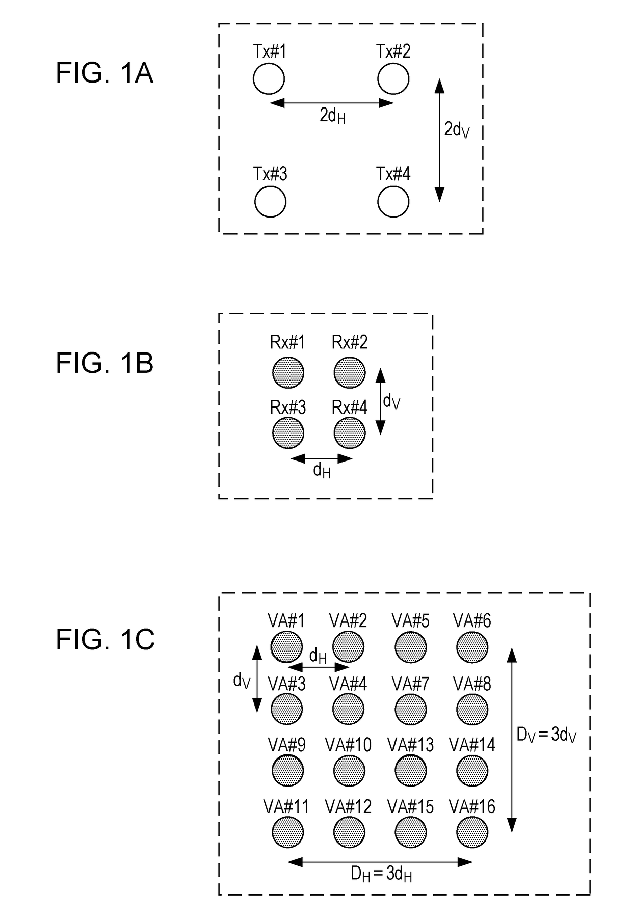
However, when the number of antennas in the transmission and reception branch is restricted to achieve cost and size reduction of the MIMO radar (for example, when the number of transmission antennas is about four and the number of reception antennas is about four), the aperture lengths in the vertical and horizontal directions are restricted in the planar virtual reception array formed by the MIMO radar.

Method used


Image

  • Radar device
  • Radar device
  • Radar device

Examples


embodiment 1

(Variation 3 of Embodiment 1)

[0256]In Embodiment 1, the radar device 10 using five or more reception antennas 202 may include three transmission antennas 106. Alternatively, the radar device 10 using five or more transmission antennas 106 may include three reception antennas 202.

[0257]Description is given below of an example of the radar device 10 which includes three transmission antennas 106 and five reception antennas 202.

[0258]FIG. 11A illustrates an arrangement example of the transmission antennas 106 and the reception antennas 202. FIG. 11B illustrates an arrangement of virtual reception array obtained from the antenna arrangement illustrated in FIG. 11A.

[0259]In FIG. 11A, the three transmission antennas 106 are denoted respectively by Tx#1 to Tx#3, and the five reception antennas 202 are denoted respectively by Rx#1 to Rx#5. In FIG. 11A, the transmission antennas Tx#1 to Tx#3 are arranged such that one antenna is arranged on the right side of the transmission antenna Tx#1 in ...

embodiment 2

(Variation 6 of Embodiment 2)

[0381]In Embodiment 2, a radar device 10 using five or more reception antennas 202 may include three transmission antennas 106. Alternatively, a radar device 10 using five or more transmission antennas 106 may include three reception antennas 202.

[0382]Description is given below of an example of the radar device 10 which includes three transmission antennas 106 and five reception antennas 202.

[0383]Moreover, there is used a MIMO array arrangement in which the size of the array element is about one wavelength (1λ) in the vertical and horizontal directions due to stacking of the antenna elements in the vertical and horizontal directions.

[0384]FIG. 22A illustrates an arrangement example of the transmission antennas 106 and the reception antennas 202. FIG. 22B illustrates an arrangement of a virtual reception array obtained from the antenna arrangement illustrated in FIG. 22A.

[0385]In FIG. 22A, the three transmission antennas 106 are denoted respectively by ...


PUM


Abstract

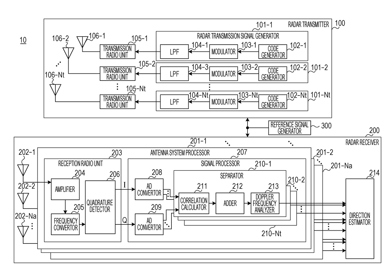
A plurality of transmission antennas include Nt1 transmission antennas arranged in a first direction and Nt2 transmission antennas arranged in a second direction orthogonal to the first direction, a plurality of reception antennas include Na1 reception antennas arranged in the first direction and Na2 reception antennas arranged in the second direction. In the first direction, an inter-element space between any two of the Nt1 transmission antennas and an inter-element space between any two of the Na1 reception antennas are each a value which is a product of a first space and an integer and are all values different from each other, and in the second direction, an inter-element space between any two of the Nt2 transmission antennas and an inter-element space between any two of the Na2 reception antennas are each a value which is a product of a second space and an integer and are all values different from each other.

Description

BACKGROUND[0001]1. Technical Field[0002]The present disclosure relates to a radar device.[0003]2. Description of the Related Art[0004]In recent years, studies are being made of a radar device using radar transmission signals with short wavelengths including microwaves and millimeter waves by which high resolution can be obtained. Moreover, there is a demand for development of a radar device (wide-angle radar device) which detects objects (targets) including not only vehicles but also pedestrians in a wide angular range to improve safety outdoors.[0005]For example, a pulse radar device which repeatedly transmits pulse waves is known as the radar device. A reception signal of a wide-angle pulse radar which detects vehicles and pedestrians in a wide angular range is a signal in which multiple reflected waves from a target (for example, a vehicle) existing in a close distance and a target (for example, a pedestrian) existing in a far distance are mixed. Accordingly, the radar device req...

Claims


Application Information

Patent Timeline
Patent Type & Authority Applications(United States)
IPC IPC(8): G01S7/28H01Q1/36
CPCH01Q1/36G01S7/28G01S13/90G01S7/02G01S7/285G01S7/352G01S13/325G01S2013/0254H01Q21/061H01Q25/00
Inventor KISHIGAMI, TAKAAKISATO, JUNJI
Owner PANASONIC HLDG CORP
Why Eureka
Try Eureka