Camera with radar system
a radar system and camera technology, applied in the field of cameras with radar systems, can solve the problems of limiting the useable depth range to a few meters, slow focus strategy, and inability to work with ultrasonic systems, etc., and achieve good correlation properties
- Summary
- Abstract
- Description
- Claims
- Application Information
AI Technical Summary
Benefits of technology
Problems solved by technology
Method used
Image
Examples
third embodiment
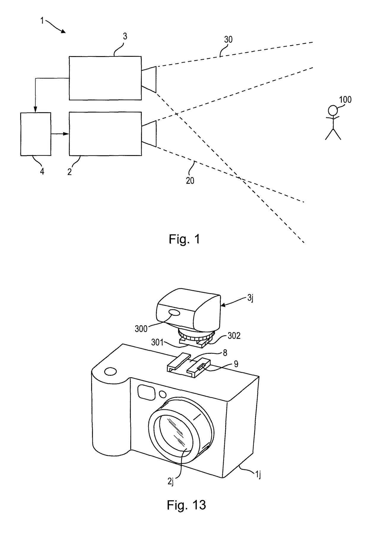
[0074]FIG. 6 shows a schematic diagram of a camera 1c according to the present disclosure. The radar system 3c comprises one (or more) transmit (Tx) antenna(s) 31, one (or more) receive (Rx) antenna(s) 32 and a radar sensor 33 (which may comprises the elements of the radar system 3a or 3b as depicted in FIGS. 3 and 4) for processing transmit and receive signals to obtain the desired radar information. The radar system 3c may generally be equipped with multiple antennas or phased array antennas collecting the direction of arrival (DoA) information from the target(s) in the scene. In still another embodiment the radar system is equipped with a single collocated antenna for transmission and reception.
[0075]The radar sensor 33 particularly records the reflected signals from the target(s). The timing of the reflected signals give the distance information to the target(s), the frequency offset or Doppler of the reflected signals give the speed information of the target(s), and the level (...
fourth embodiment
[0082]FIG. 7 shows a schematic diagram of a camera 1d according to the present disclosure. In this embodiment the optical system 2d comprises a zoom unit 25 (also called lens focal length trimmer) for changing the focal length (i.e. the zoom factor) of said optical system 2d. If the distance and the size (or dimensions) of the main target in the scene is known, the focal length or zoom factor can be adjusted to have the object of interest in optimal size on the image. Information to interpret or estimate the dimensions of the image and / or of targets in the optical field of view may also be taken from the image sensor. The control unit 4 is thus configured to control the zoom unit 25 based on the distance information and / or dimension information obtained by the radar system 3d.
[0083]For enabling a fast zooming of the optical system on a desired target in the scene, the control unit 4 thus obtains the absolute distance of the target and / or dimension information of the target from the...
fifth embodiment
[0084]FIG. 8 shows a schematic diagram of a camera 1e according to the present disclosure. In this embodiment a camera manipulation unit 7 (as part of the camera 1e or as external unit) is provided for moving and / or tilting the camera 1e, or at least the optical system 2e of the camera 1e, with respect to a reference point, e.g. with respect to a fixation of the camera 1e, such as a rotary tripod, on which the camera 1e is mounted. This enables to have the target of interest in the center of the image. For fast control of the manipulation unit 7, which may be a motor or other actuator mounted at or within the camera or mounted at a rotary tripod, the control unit looks up the manipulator position in an LUT stored in the memory 6e based on the direction of the target obtained from the radar system 3e. For this purpose the radar system 3e is preferably equipped with multiple antennas or phased array antennas collecting the direction of arrival (DoA) information from the target(s) in t...
PUM
 Abstract
Description
Claims
Application Information
 - R&D
- Intellectual Property
- Life Sciences
- Materials
- Tech Scout
- Unparalleled Data Quality
- Higher Quality Content
- 60% Fewer Hallucinations
Browse by: Latest US Patents, China's latest patents, Technical Efficacy Thesaurus, Application Domain, Technology Topic, Popular Technical Reports.
© 2025 PatSnap. All rights reserved.Legal|Privacy policy|Modern Slavery Act Transparency Statement|Sitemap|About US| Contact US: help@patsnap.com


