
Hybrid vehicle with multi-zone cabin cooling and integrated battery cooling

a hybrid vehicle and cabin cooling technology, applied in battery/fuel cell control arrangement, battery/fuel cell, electrochemical generators, etc., can solve the problems of reducing battery charge efficiency, power generation, impede battery performance, etc., and achieve the effect of reducing the need

Inactive Publication Date: 2017-03-30
FORD GLOBAL TECH LLC
View PDF14 Cites 23 Cited by
  • Summary
  • Abstract
  • Description
  • Claims
  • Application Information

AI Technical Summary

Benefits of technology

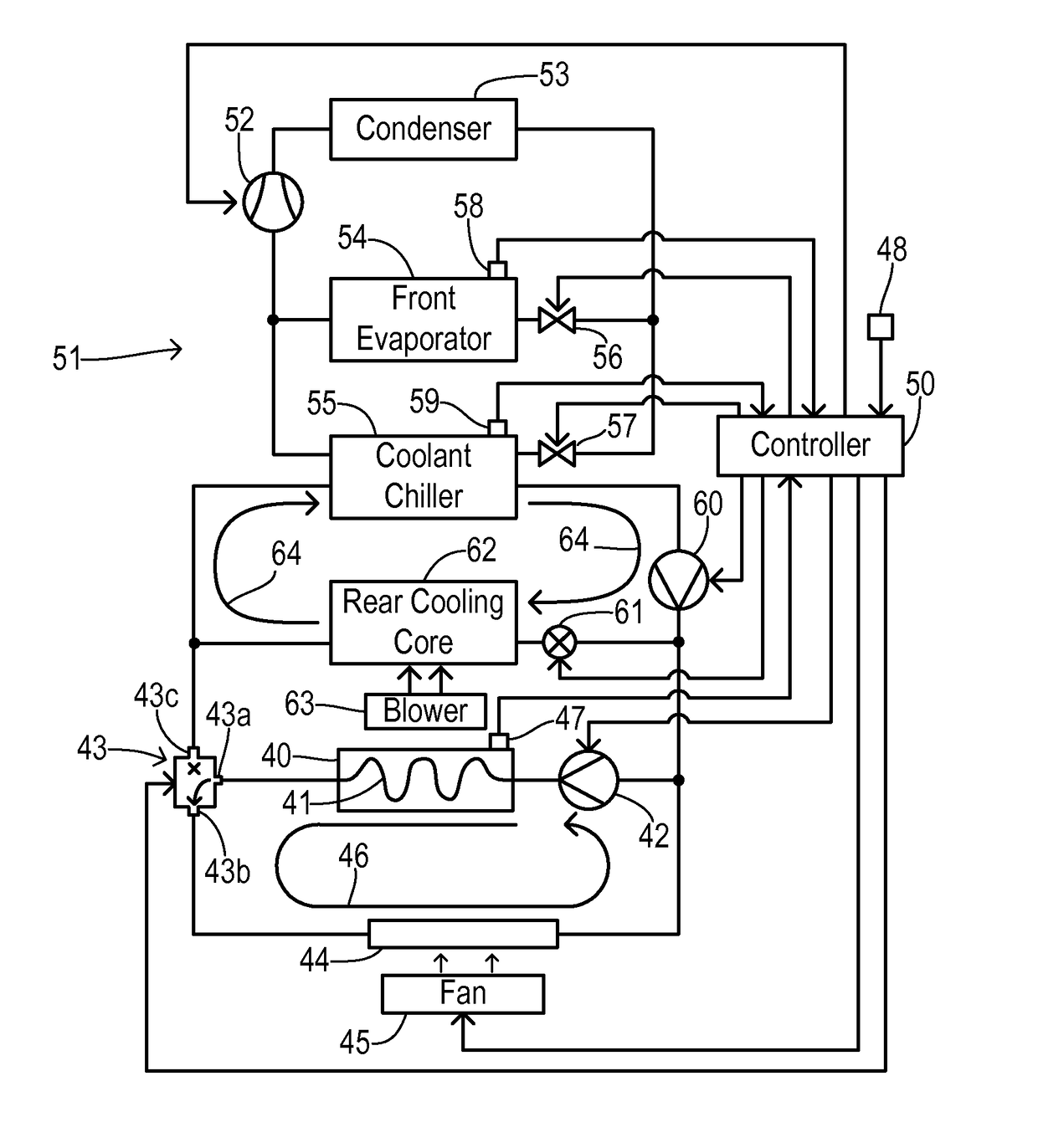
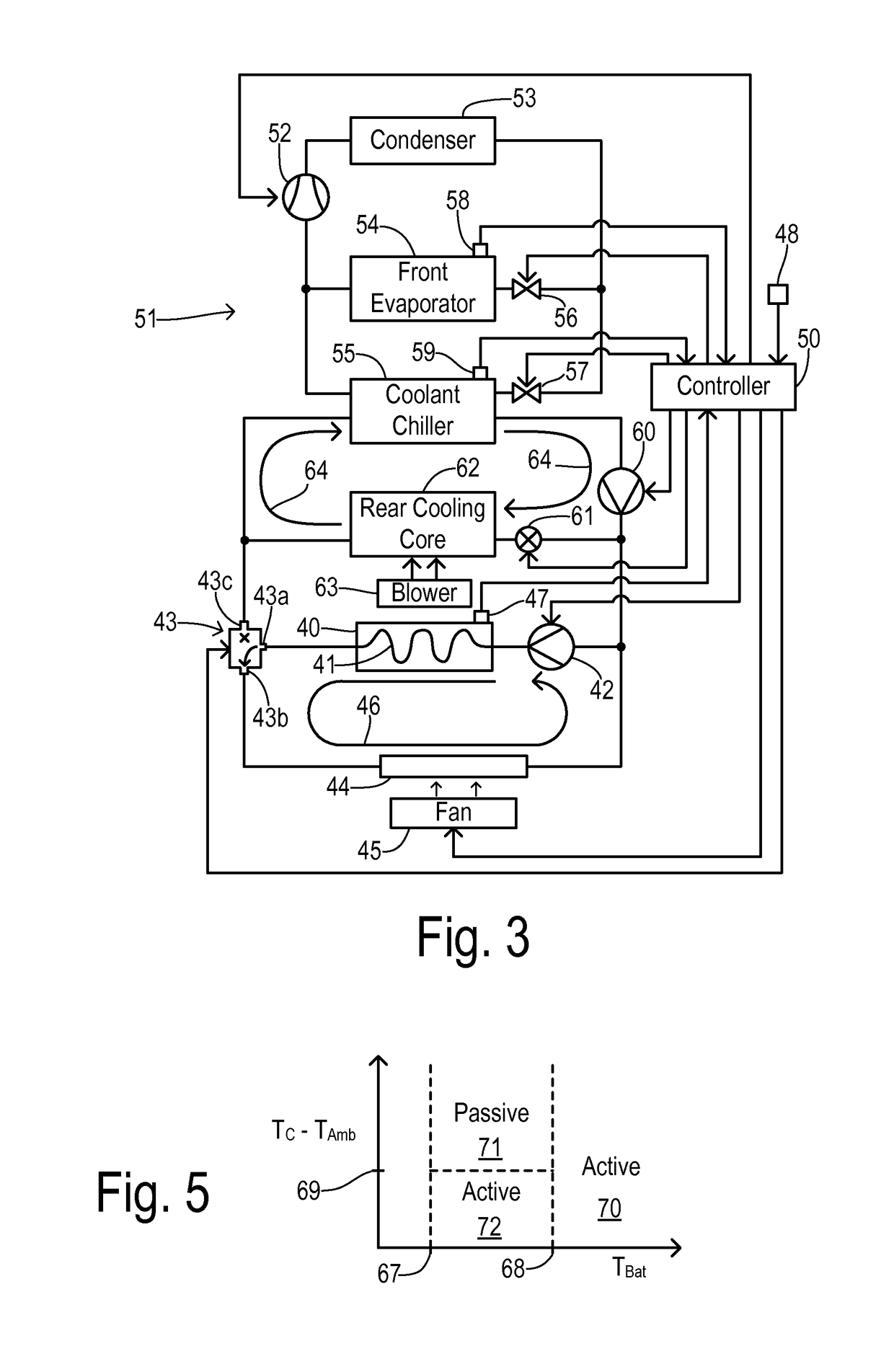
The invention is about a cooling system for electric vehicles that uses a refrigerant-to-coolant heat exchanger to cool the battery and a coolant-to-air heat exchanger to cool the passenger cabin. The system also has a passive cooling mode for the battery, a shared cooling subsystem with a compressor and condenser, and a battery pump to circulate the coolant. The invention helps to reduce the need for refrigerant-based evaporators and improves the efficiency of the cooling system.

Problems solved by technology

Increases in battery temperature can reduce battery charge efficiency and impede battery performance.
If the battery is not cooled, the power generation, battery life, and fuel economy may suffer.
In an electrified vehicle with multiple passenger cooling zones, the demand on the shared refrigerant supply subsystem can become large.
Increasing the size of shared cooling subsystem components (e.g., compressor, condenser, evaporator) can be undesirable due to losses in efficiency and increases in cost.
As the number of evaporators grows and the needed capacity of other air conditioning components is increased, additional problems can arise such as increased compressor oil entrapment, more costly and complex refrigerant distribution, and difficulty balancing peak consumption for different sections of the A / C system.

Method used


Image

  • Hybrid vehicle with multi-zone cabin cooling and integrated battery cooling
  • Hybrid vehicle with multi-zone cabin cooling and integrated battery cooling
  • Hybrid vehicle with multi-zone cabin cooling and integrated battery cooling

Examples


Embodiment Construction

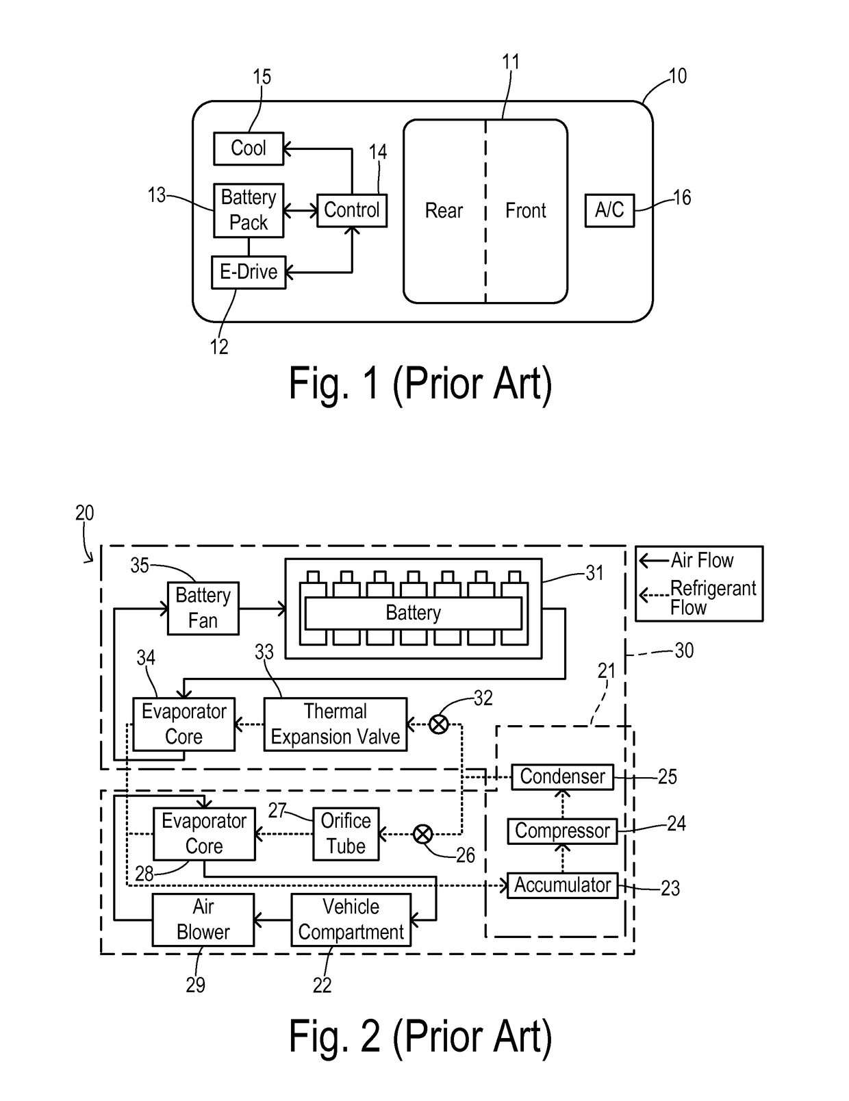
[0019]Referring to FIG. 1, an electrified vehicle 10 has a passenger cabin 11 with front and rear zones as indicated. An electric drive 12 (e.g., an inverter-driven traction motor) receives electrical power from a battery pack 13. A controller 14 may include a battery control module for monitoring battery performance (including battery temperature) and a system controller for operating the inverter. A battery cooling system 15 provides a cooling fluid (such as a chilled liquid coolant or a cooled air flow) to battery pack 13 under control of controller 14. Conventional systems have utilized an independent source of cooled air in cooling system 15 and have used a shared cooling system with a passenger A / C system 16 (for either air-cooled or liquid-cooled batteries).

[0020]FIG. 2 shows a prior art shared cooling system 20 including a passenger compartment air conditioning (A / C) system 21 capable of cooling passenger compartment 22. The passenger compartment A / C system 21 includes an ac...


PUM


Abstract

Cooling of a battery pack of an electrified vehicle is performed with an optimized energy usage and with minimal impact on cooling of the passenger cabin. Refrigerant from a condenser in an air conditioning system is evaporated in a front evaporator to cool a main air flow in a front cabin zone. The refrigerant is evaporated in a coolant chiller to cool a liquid coolant. The liquid coolant is pumped from the chiller to a rear exchanger to cool a rear air flow in a rear cabin zone. The liquid coolant is pumped from the chiller to the battery when a battery temperature and an ambient air temperature correspond to an active cooling mode. The coolant is pumped between the battery and a passive radiator instead of the chiller when the battery coolant temperature and the ambient air temperature correspond to a passive cooling mode.

Description

CROSS REFERENCE TO RELATED APPLICATIONS[0001]Not Applicable.STATEMENT REGARDING FEDERALLY SPONSORED RESEARCH[0002]Not Applicable.BACKGROUND OF THE INVENTION[0003]The present invention relates in general to battery cooling in electrified vehicles, and, more specifically, to a liquid-cooled battery with active and passive cooling modes.[0004]When an electrical storage battery (e.g., battery pack) is used to provide power to an electric motor to drive an electrified vehicle (e.g., hybrid electric or full electric), the temperature of the battery can increase when the motor is operating for extended periods of time. The battery pack is usually installed in a relatively small, enclosed space which tends to retain the heat generated. Increases in battery temperature can reduce battery charge efficiency and impede battery performance. If the battery is not cooled, the power generation, battery life, and fuel economy may suffer.[0005]Passenger vehicles typically have a passenger air conditi...

Claims


Application Information

Patent Timeline
Patent Type & Authority Applications(United States)
IPC IPC(8): B60H1/00B60H1/32
CPCB60H1/00278B60H1/00392B60H1/321B60H2001/3272B60H2001/3255B60H2001/3266B60H1/323H01M10/613H01M10/625H01M10/635H01M10/637H01M10/6556H01M10/6563B60L58/26B60H1/00385B60H1/3204H01M2220/20B60H2001/00307Y02T10/70Y02E60/10B60H1/22B60K1/04
Inventor BLATCHLEY, TIMOTHY N.JACKSON, KEN J.PORRAS, ANGEL F.
Owner FORD GLOBAL TECH LLC
Learn More