
Apparatus for Changing the Angle of Inclination in Wind Turbines

Inactive Publication Date: 2017-04-06
NABRAWIND TECH SL
View PDF3 Cites 0 Cited by
  • Summary
  • Abstract
  • Description
  • Claims
  • Application Information

AI Technical Summary

Benefits of technology

The patent describes a wind turbine with an improved sensor system at the front of the nacelle to measure the wind direction and speed. This helps to increase the accuracy of the yaw and tilt systems, which are important for ensuring the turbine operates safely and efficiently. The sensor system is placed at the front of the nacelle, so it is not affected by the rotor blades, which can cause distortion in the measurements. By collecting data with a certain degree of anticipation, the system can also reduce extreme loads caused by occasional wind gusts and help alleviate fatigue loads. These improvements can lead to cost reductions for components that are designed to withstand wind loads.

Problems solved by technology

In this case the tilt causes a certain horizontal wind misalignment, which worsens when the wind has vertical components (particularly on complex terrain).
The state of the art in tilt variation systems comprises a significant number of patents, though most are for upwind wind turbines and are complex control systems that take different measurements and engage the device for changing the tilt angle to improve power generation performance.
In view of the foregoing, the search for background developments in this regard is limited to tilt control systems presenting some detailed solution that applies to downwind wind turbines.
However, the system that enables the actuators to rotate according to the yawing is a complex system of notched wheels that move the nacelle (4) on the actuator support (13).
The layout of the forked articulation varies the entire wind turbine and fully conditions the entire design of the nacelle or frame, greatly complicating it because it does not permit load reactions on the parts nearest the tower (outside) but rather on the central axis.
This will render said structure more complicated and expensive.

Method used


Image

  • Apparatus for Changing the Angle of Inclination in Wind Turbines
  • Apparatus for Changing the Angle of Inclination in Wind Turbines
  • Apparatus for Changing the Angle of Inclination in Wind Turbines

Examples


Embodiment Construction

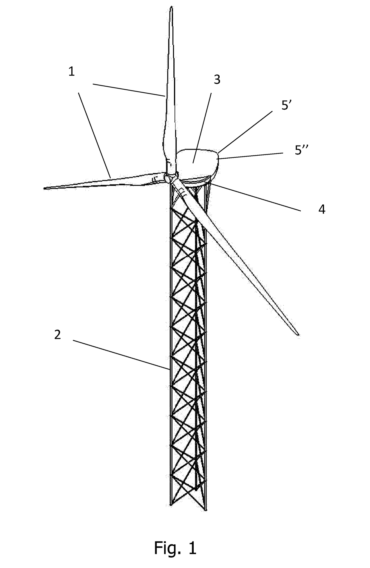
[0028]FIG. 1 illustrates a wind turbine in which a device for changing the tilt angle is installed on a horizontal axis with at least two blades 1 oriented with the wind and standing on a lattice tower 2 having three legs. There is a ringed connection part 4 between the nacelle 3 and tower 2. Two anemometers are installed at the front end of the nacelle 3, one for measuring the horizontal component 5) and the other for measuring the vertical component 5″. Measurements obtained by the anemometers may be used by a control system to control the amount the nacelle 3 is tilted with respect of the horizontal ground plane.

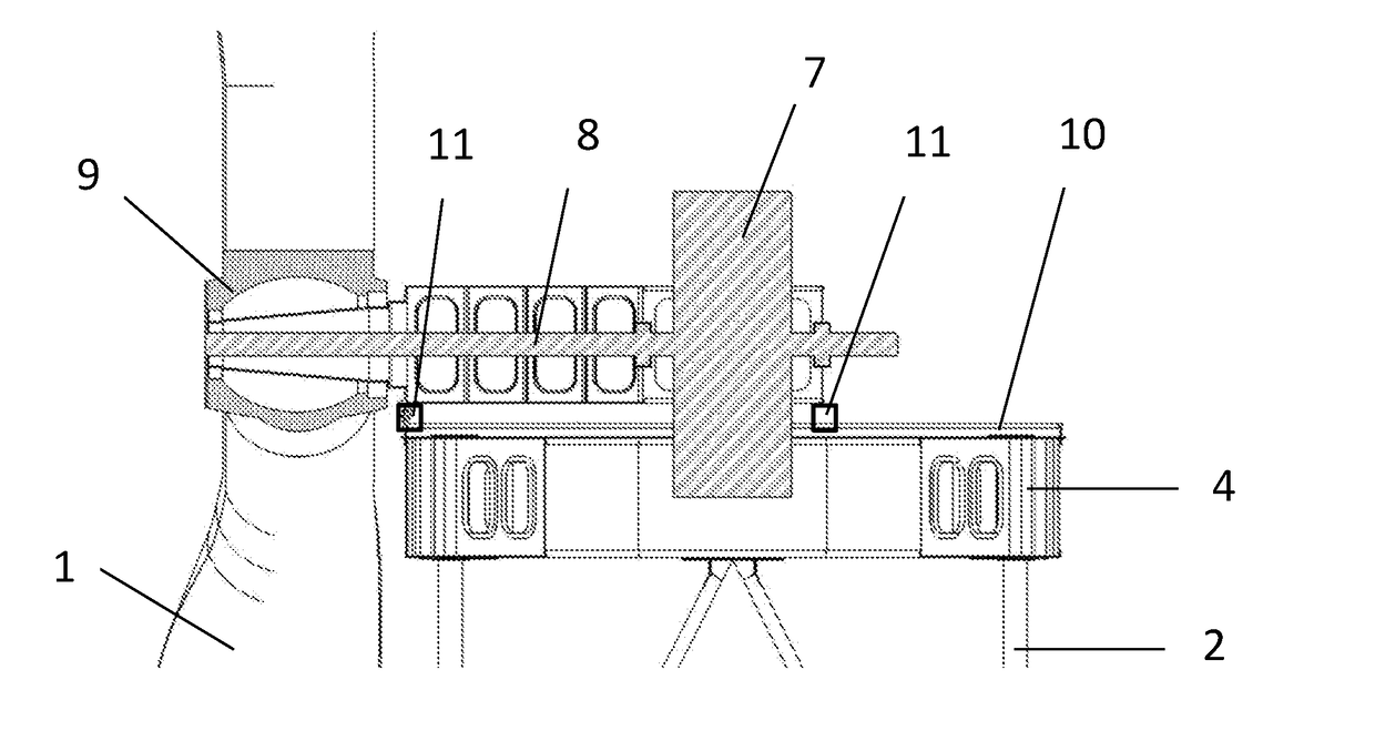
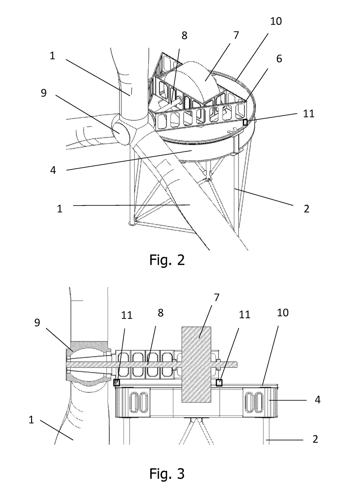
[0029]As depicted in FIGS. 2 and 3, the lattice tower 2 supports the ringed connection part 4 upon which a triangular bench 6 is seated and houses the generator 7 and main shaft 8, and supports the rotor 9 on one end. The top part of the ringed connection part 4 has a ring or rolling track 10 that forms part of the yaw system. This yaw system comprises the aforementioned ...


PUM


Abstract

A device for changing the angle of inclination in wind turbines. According to one aspect the device is formed by a connection part having a peripheral rolling ring on which three rolling supports are arranged. The rolling supports are attached to a bench that supports the rotor of the wind turbine. Each of a plurality of plates on the bench supports at least one cylinder that operates on a piston that passes through the plate. An end of the piston is coupled to a respective one of the rolling supports in an articulated manner. The cylinders are configured to operate on the pistons to cause the bench to tilt with respect to the connection part.

Description

CROSS-REFERENCE TO RELATED APPLICATIONS[0001]This application relates to and claims the benefit and priority to International Application No. PCT / ES2014 / 000106, filed Jun. 27, 2014, which is incorporated herein by reference in its entirety.FIELD[0002]The present disclosure is encompassed in the field of wind turbines and, more specifically, the device enabling variation of the inclination angle (tilt) that the rotor axis forms with the horizontal plane.BACKGROUND[0003]The rotor axis tilt was not initially intended for alignment with the wind direction. Instead it was conceived to increase the space between the blades and tower to prevent collisions. This increase is very significant upwind, since the maximum blade deflection bends toward the tower. In this case the tilt causes a certain horizontal wind misalignment, which worsens when the wind has vertical components (particularly on complex terrain). The effects are nevertheless reversed with downwind rotors. Firstly, the maximum b...

Claims


Application Information

Patent Timeline
IPC IPC(8): F03D7/02F03D9/00F03D13/20
CPCF03D7/0204F03D9/002F03D13/20F03D1/00F05B2240/2213F05B2270/321F03D7/02F03D9/25Y02E10/72Y02E10/728
Inventor SANZ PASCUAL, ENEKOSAVII COSTA, HELY RICARDO
Owner NABRAWIND TECH SL
Learn More