
Gas ejection duct with acoustic treatment, an aircraft, and a method of fabricating such a duct

a technology of gas ejection duct and acoustic treatment, which is applied in the direction of efficient propulsion technology, machines/engines, instruments, etc., can solve the problems of difficult to fabricate sheets, difficult to find different cavities, and pain for humans to hear the noise of engines used in aviation

Inactive Publication Date: 2017-04-20
EUROCOPTER
View PDF10 Cites 12 Cited by
  • Summary
  • Abstract
  • Description
  • Claims
  • Application Information

AI Technical Summary

Benefits of technology

The patent is about a new gas ejection duct with acoustic treatment that uses a new Helmholtz resonator shape (parallelepiped) that allows for the fabrication of a mesh without using surfaces that are flat. This new shape optimizes the acoustic treatment by allowing for an unlimited number of cavities to be aligned transversely and in elevation without loss of treated surface area. The uses a material called Inconel 718 powder which is strong and can withstand external environments while using small thicknesses. Overall, this innovation allows for the fabrication of complex parts with relatively low costs.

Problems solved by technology

The engines used in aviation can produce noise that is painful for a human to hear.
Nevertheless, making different cavities turns out to be difficult when using metal sheets that are brazed to one another.
In addition, assembling sheets requires numerous fabrication operations.
In particular, such assembly can require fine metal sheets to be brazed together, which is difficult.
Consequently, making a gas ejection duct, and in particular a nozzle, that is provided with such acoustic treatment means can be difficult and / or expensive.

Method used


Image

  • Gas ejection duct with acoustic treatment, an aircraft, and a method of fabricating such a duct
  • Gas ejection duct with acoustic treatment, an aircraft, and a method of fabricating such a duct
  • Gas ejection duct with acoustic treatment, an aircraft, and a method of fabricating such a duct

Examples


Embodiment Construction

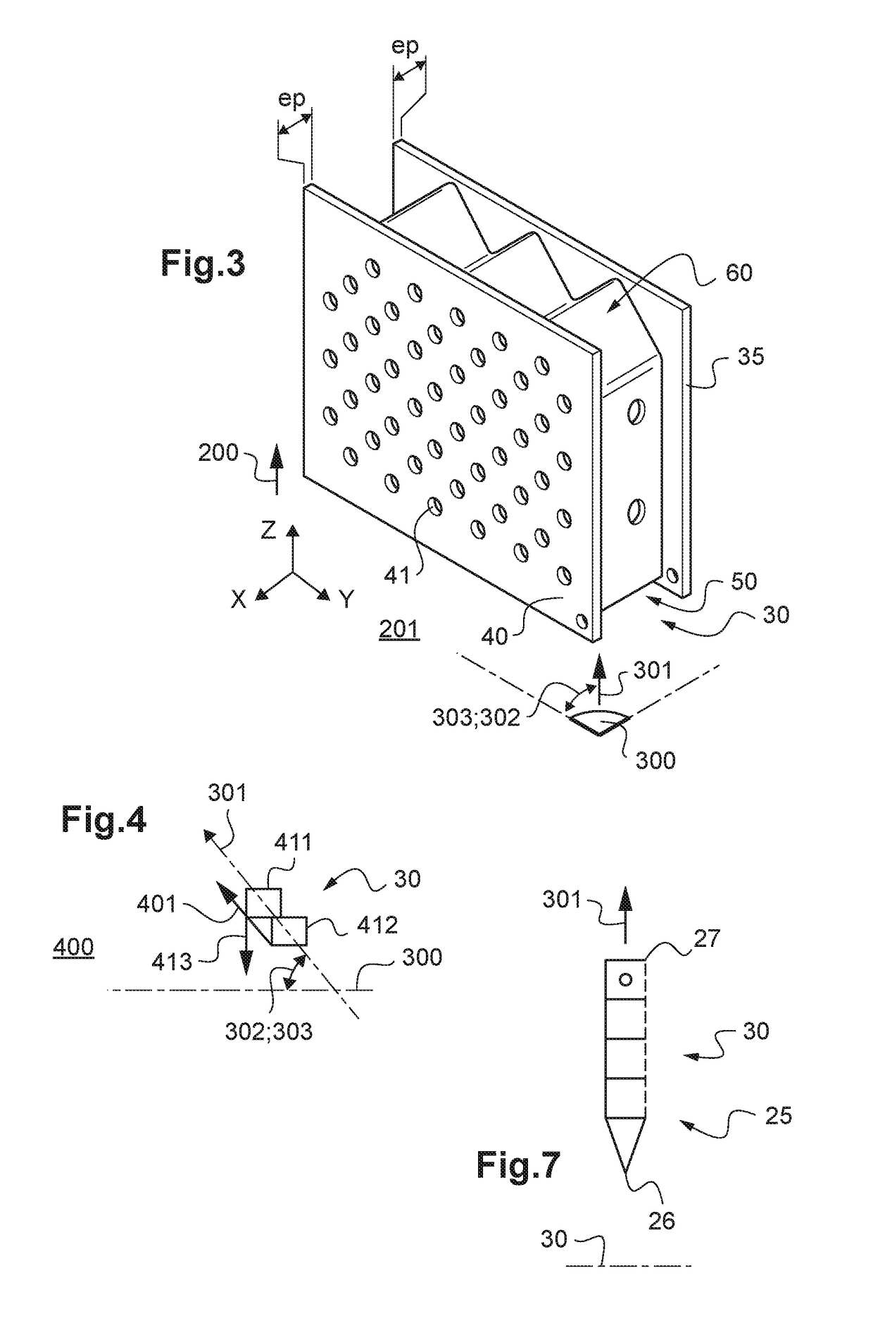
[0090]It should be observed that three mutually orthogonal directions X, Y, and Z are shown in some of the figures.

[0091]The direction X is said to be longitudinal. Another direction Y is said to be transverse. Finally, a third direction Z is said to be in elevation, and corresponds to the height dimensions of the structures described.

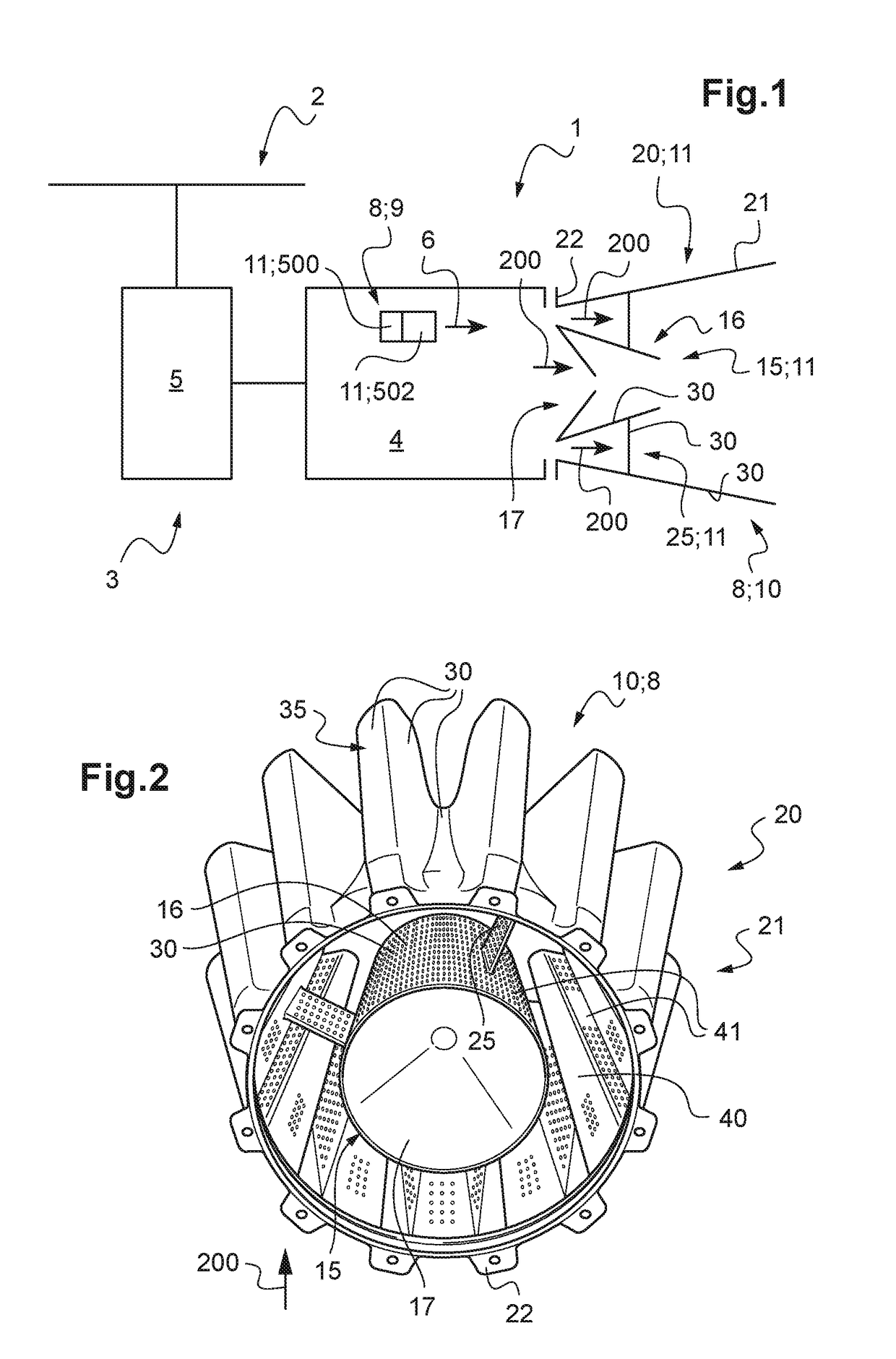
[0092]FIG. 1 shows an aircraft 1 of the invention.

[0093]This aircraft 1 has a power plant 3 having at least one engine 4. For example, the engine acts via a main gearbox 5 to drive a rotor 2 that participates at least to providing the aircraft with lift. The engine 4 may be a fuel burning engine ejecting gas 200, such as piston engine or a turboshaft engine.

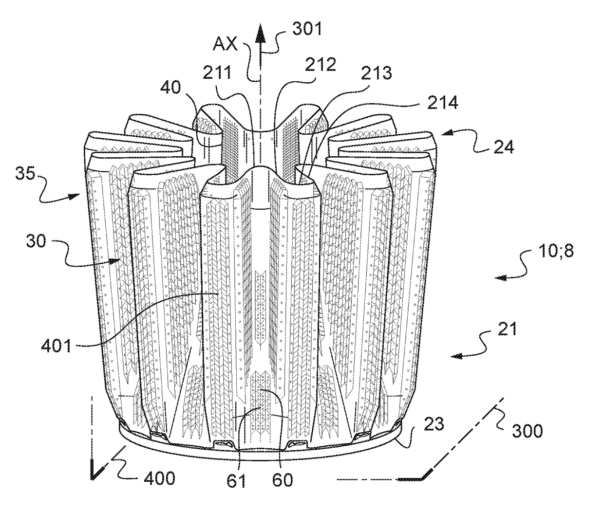
[0094]In order to discharge gas from the engine, the aircraft 1 is provided with a gas ejection duct 8 with acoustic treatment.

[0095]Such a gas ejection duct 8 with acoustic treatment may be a gas ejection nozzle 10 with acoustic treatment directing the gas towards the outside of the aircraft, e.g. ...


PUM

PropertyMeasurementUnit
Thicknessaaaaaaaaaa
Angleaaaaaaaaaa
Angleaaaaaaaaaa

Abstract

A gas ejection duct with acoustic treatment provided with at least one wall referred to as an “acoustic” wall for coming into contact with the gas. The acoustic wall comprises an inner skin and an outer skin that are spaced apart at least in part by a space, the acoustic wall including at least one internal mesh in the space, the mesh defining a plurality of cavities. Each cavity has the shape of a parallelepiped, each mesh extending longitudinally in a direction referred to as the “fabrication” direction that presents an acute angle greater than or equal to a predetermined angle relative to a horizontal plane, each of the inner and outer skins presenting an acute angle of inclination greater than or equal to the at least one predetermined angle relative to the horizontal plane.

Description

CROSS REFERENCE TO RELATED APPLICATION[0001]This application claims priority to French patent application No. FR 15 02204 filed on Oct. 20, 2015, the disclosure of which is incorporated in its entirety by reference herein.BACKGROUND OF THE INVENTION[0002](1) Field of the Invention[0003]The present invention relates to a gas ejection duct with acoustic treatment, and to an aircraft having such a duct. The invention also relates to a method of fabricating such a duct.[0004]The invention lies in the technical field of gas ejection ducts for aircraft.[0005](2) Description of Related Art[0006]An aircraft usually has an engine contributing to providing the aircraft with propulsion or indeed lift. For example, a rotorcraft may have a fuel burning engine that rotates a rotor contributing at least to providing the aircraft with lift.[0007]The engine generates exhaust gas that is expelled out from the aircraft by an ejection system. On an aircraft, a gas ejection system may include a duct com...

Claims


Application Information

Patent Timeline
IPC IPC(8): F02C7/24F01D25/00C22C19/05B22F3/105B33Y10/00B33Y80/00F01D25/30G10K11/16
CPCB33Y80/00C22C19/056F05D2220/32F02C7/24B33Y10/00F01D25/005G10K11/161B22F3/1055F01D25/30B64D33/06F02K1/827F05D2260/963Y02T50/60Y02P10/25B22F10/28
Inventor LOEWENSTEIN, PHILIPPEHERFORT, REMI
Owner EUROCOPTER
Learn More