Method for selecting an optimized trajectory

a technology of optimizing and selecting the path, applied in the direction of navigation instruments, process and machine control, etc., can solve the problems of increasing the risk of automatic control vehicle causing traffic interference, need can again arise, and the need for a travel path can be rescheduled, so as to increase the probability of ascertaining the travel path and the number of travel trajectories

Active Publication Date: 2017-04-20
ROBERT BOSCH GMBH
View PDF3 Cites 82 Cited by
  • Summary
  • Abstract
  • Description
  • Claims
  • Application Information

AI Technical Summary

Benefits of technology

[0031]This embodiment offers the advantage that multiple target sites, and thus also a greater number of travel trajectories, can be rated; this in turn increases the probability of ascertaining a travel trajectory that can be traveled as safely as possible.
[0032]In an advantageous refinement of the method, selection of one of the travel trajectories is accomplished based additionally on the rating of the at least two target sites.
[0033]This embodiment offers the advantage that a rating of the target sites is also included in the rating of the travel trajectories. Different criteria for rating of the target sites can be utilized in this context. For example, the possibility of localizing the target site can be taken into consideration so that, if applicable, an emergency call can be made indicating the exact vehicle position. The probability of a collision and / or interference with other traffic participants can furthermore be included in the rating of the target site. Preferred target sites would then be, for example, parking facilities, shoulder, parking lanes, or emergency stopping areas. Information regarding reachable target sites can be requested, for example, from a map server.

Problems solved by technology

If that functionality is limited, a need can again arise.
If an automatically controlled vehicle has difficulty ascertaining its position and / or travel path, the risk of the automatically controlled vehicle causing traffic interference and / or an accident then rises sharply.

Method used


Image

  • Method for selecting an optimized trajectory
  • Method for selecting an optimized trajectory
  • Method for selecting an optimized trajectory

Examples


Embodiment Construction

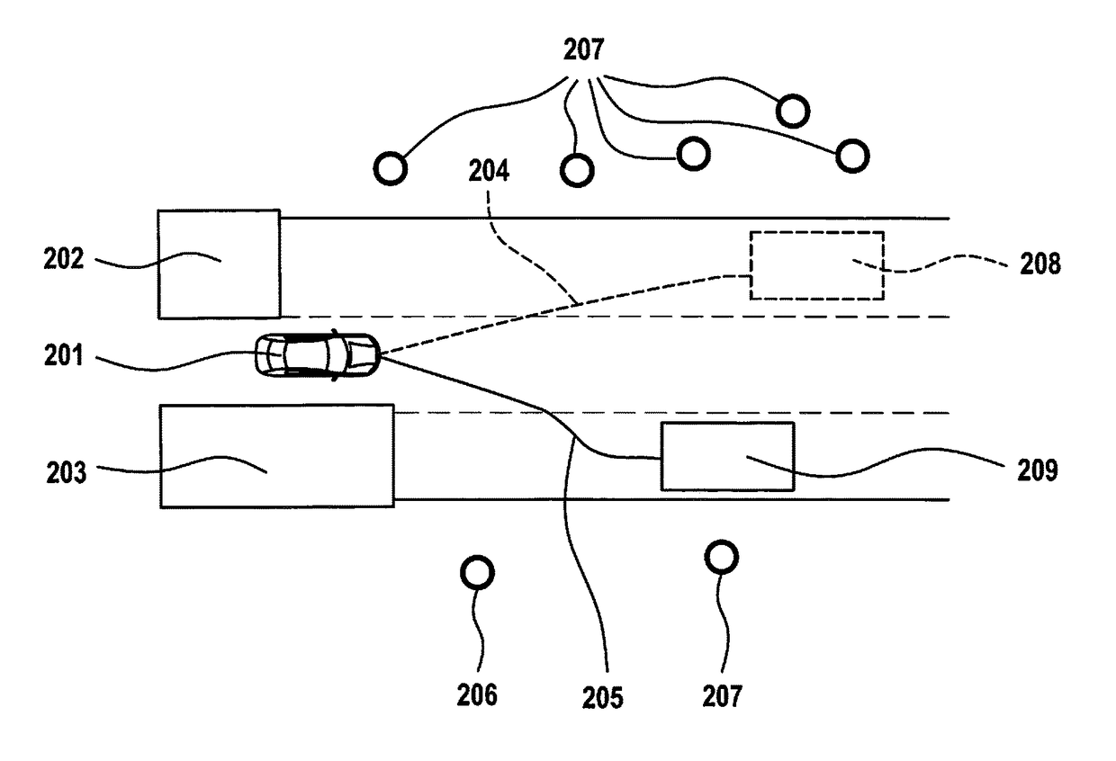
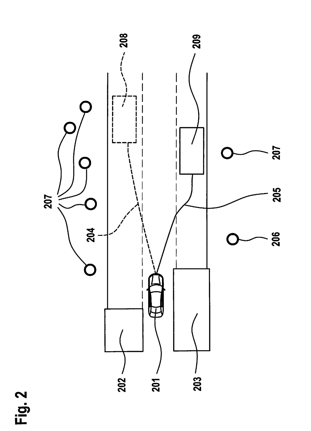
[0043]FIG. 1 depicts an example of execution of the example method in a vehicle 201. The vehicle is equipped with a corresponding first apparatus on which a computer program is configured to execute the method. Vehicle 201 is furthermore equipped with sensors for environmental sensing, and optionally also with sensors for interior sensing. A second apparatus can also be provided in vehicle 201, which apparatus receives the signal, generated on the basis of a selected travel trajectory 204, 205, of the first apparatus and, based on that signal, carries out an application of control to corresponding actuators of vehicle 201 in order to guide the latter automatically along the selected trajectory 204, 205.

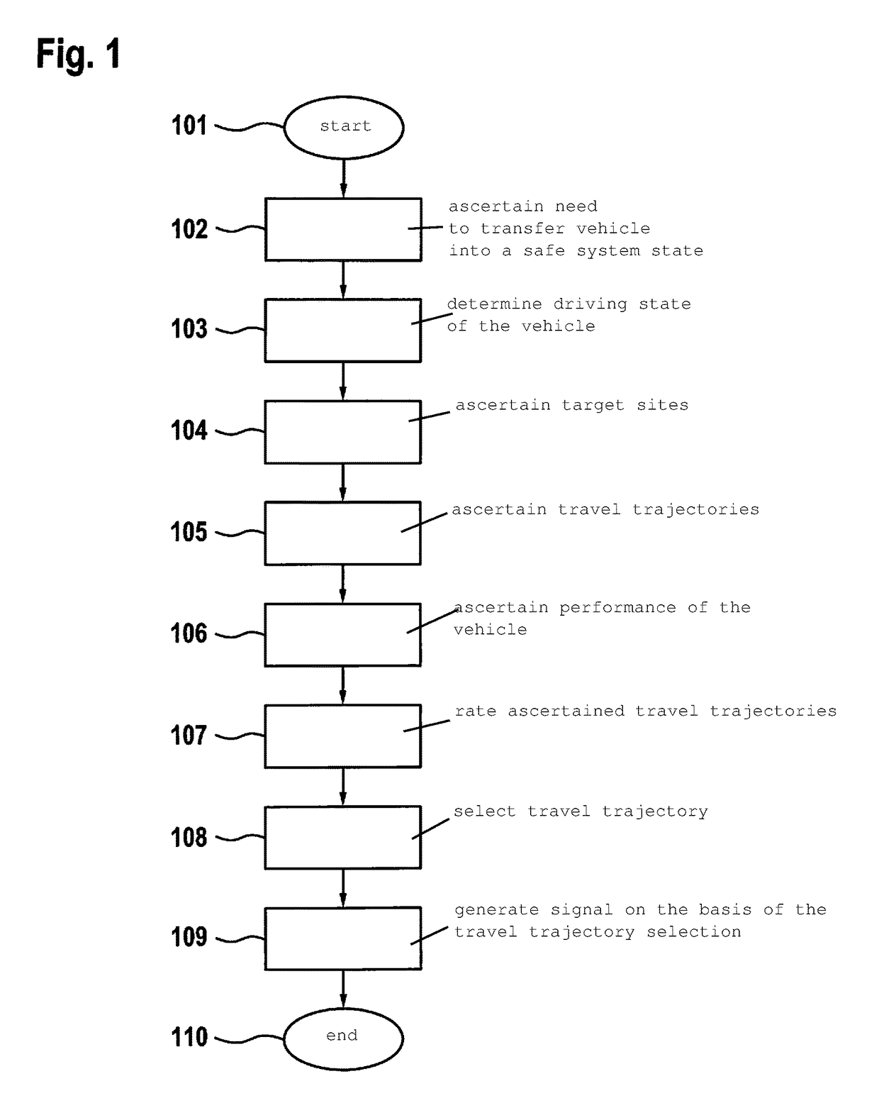
[0044]The method starts in step 101.

[0045]In step 102 the need to transfer vehicle 201 into a safe system state is ascertained. For this, the driver state and / or the vehicle state is ascertained. The interior sensing system of vehicle 201 is used to ascertain the driver state.

[0046]Mo...


PUM


Abstract

A method for generating a signal for transferring a partly or highly automated vehicle into a safe system state at a target site. First, a need to transfer the vehicle into a safe system state is ascertained. A vehicle state is then determined, the vehicle state encompassing the current vehicle position. At least one target site is ascertained. Travel trajectories are ascertained from the current vehicle position to the at least one target site. The travel trajectories are related. One of the travel trajectories is selected based on the rating that has been carried out. A signal is generated on the basis of the selected travel trajectory.

Description

CROSS REFERENCE[0001]The present application claims the benefit under 35 U.S.C. §119 of German Patent Application No. DE 102015220360.3 filed on Oct. 20, 2015, which is expressly incorporated herein by reference in its entirety.FIELD[0002]The present invention relates to a system for enhancing the safety of partly or highly automated vehicles in the event of a system error.BACKGROUND INFORMATION[0003]German Patent Application No. DE 10 2012 008 090 A1 describes a method or emergency stop assistant for carrying out a secure emergency stop maneuver of a traveling vehicle. In this, the driver is monitored, and vehicle state data are generated from which the degree of driving fitness is determined. What then occurs that the vehicle is transferred into an automatic driving mode if the degree of driving fitness of the driver falls below a predefined threshold, and a secure emergency stop maneuver is executed. In this context, a minimum-risk stoppage position is determined for the vehicle'...

Claims


Application Information

Patent Timeline
Patent Type & Authority Applications(United States)
IPC IPC(8): G05D1/00G01C21/34B60W40/08G05D1/02G01S13/931G01S15/931G01S17/931
CPCG05D1/0061G05D1/0214G08G1/16B60W40/08G05D1/0088G01C21/3407B60W30/08G08G1/166B60W2556/50B62D15/00B62D15/0285G01S13/931G01S15/931G01S2007/52009G01S2007/4975G05D2201/0213B60K28/06B60K28/14B60W2540/26B60W50/029G01S2013/9324G01S2013/9323G01S17/931B60W2554/00B60W60/0011B60W60/0015G01S7/4039G06V20/597B60W30/06B60W50/02B60W2040/0818B60W2050/0071B60W30/00B60W2540/223B60W2540/225B60W60/007B60W2540/221B60W2554/406
Inventor ROHDE, JANMIELENZ, HOLGER
Owner ROBERT BOSCH GMBH
Why Eureka
Try Eureka