
Autonomous vehicle with improved simultaneous localization and mapping function

a technology of simultaneous localization and mapping function, applied in the field of autonomous vehicles, can solve the problems of inefficient dedicated area work, inconvenient use, and inability to accurately determine the position/course/altitude of the vehicle, so as to improve the efficiency and improve the slam results. the effect of improving efficiency

Active Publication Date: 2017-04-20
HONDA RES INST EUROPE
View PDF5 Cites 19 Cited by
  • Summary
  • Abstract
  • Description
  • Claims
  • Application Information

AI Technical Summary

Benefits of technology

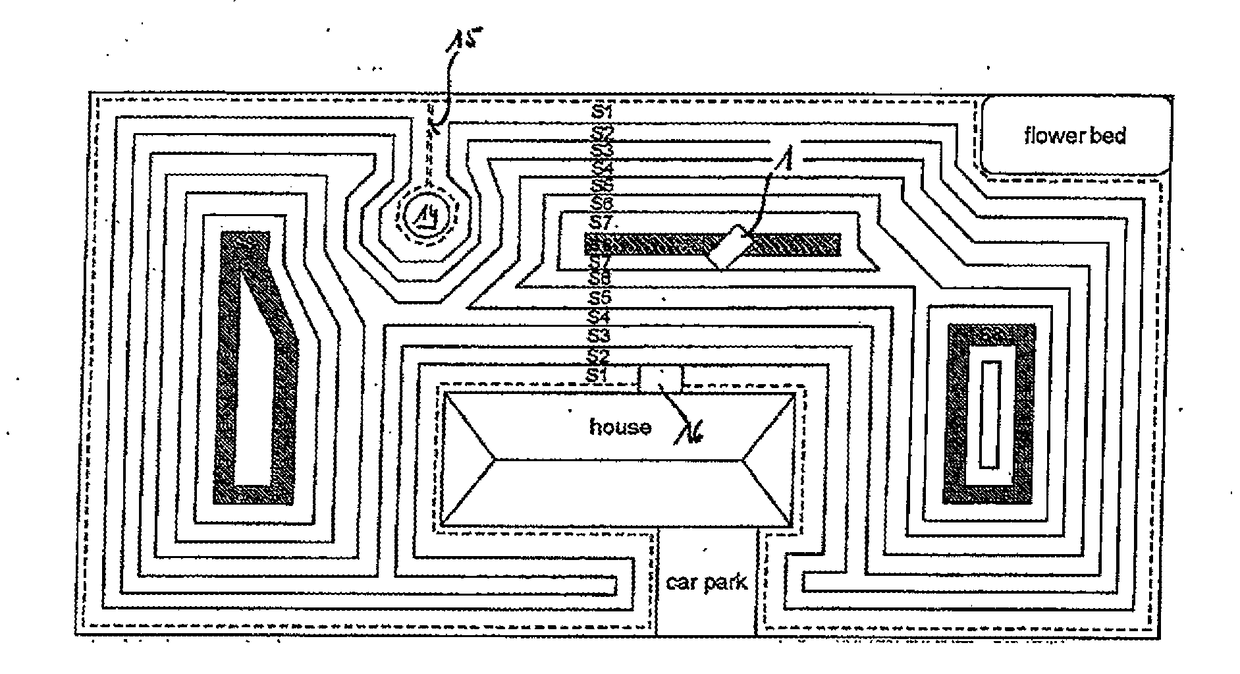
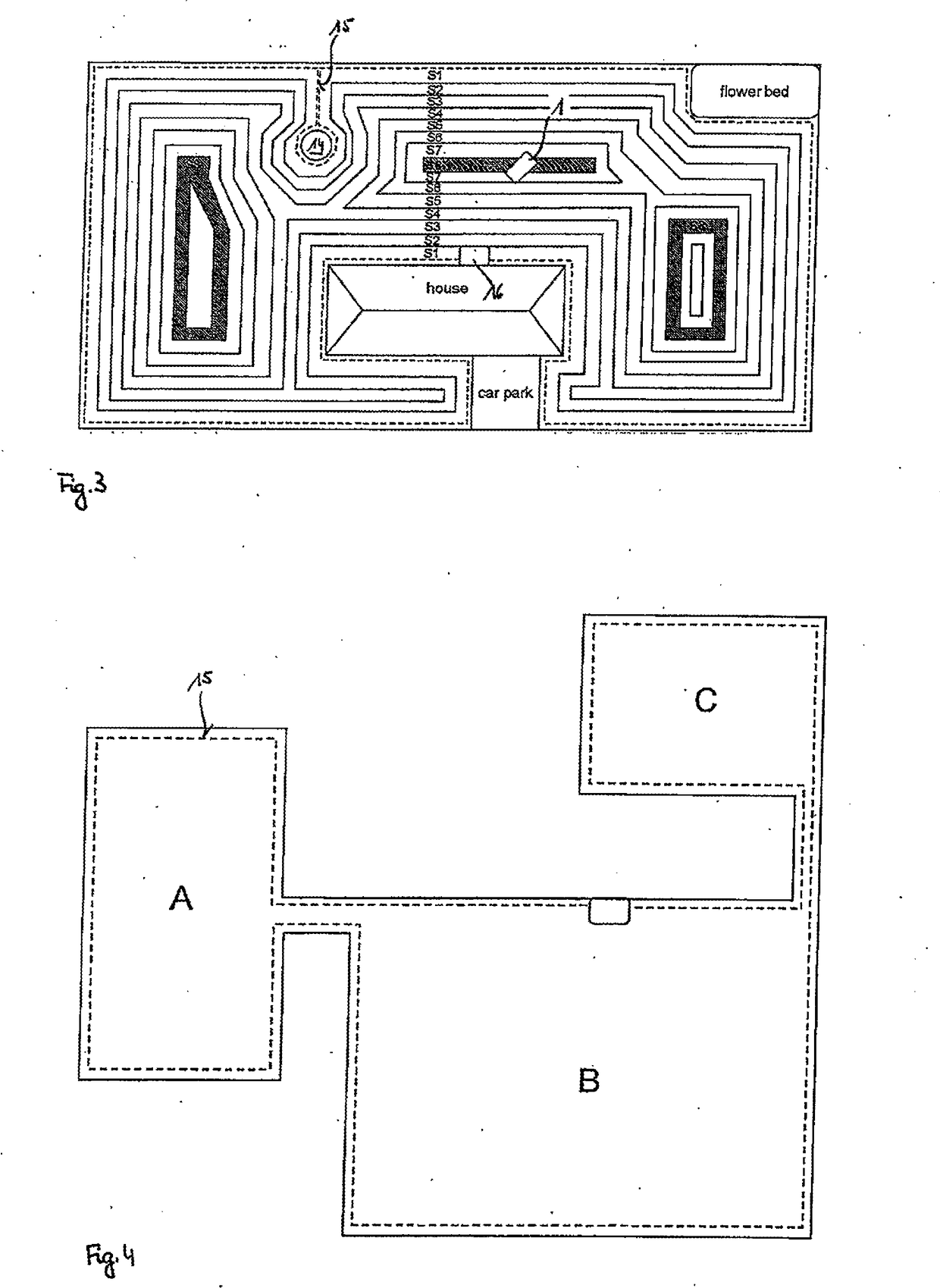
The patent text describes a system for improving the stability and accuracy of SLAM (Simultaneous Localization and Mapping) in gardening tools such as autonomous lawn mowers. The system uses both environmental sensors and distance signals to create a more robust SLAM result. This allows for efficient mowing of complex areas by ensuring that the mower doesn't waste time in areas that have been mowed too much or doesn't mow areas that have been previously mowed. The system also uses electromagnetic field sensors to obtain a direction of the mower even when it's not moving, and boundary wire sensors to improve the SLAM results. The control unit for the mower also generates control signals to lead to areas that have insufficient mowing times, improving the overall mowing result by ensuring equalization of mowing times over all segments of the area.

Problems solved by technology

Nevertheless, there are some disadvantages that might be annoying for some users.
Maybe the biggest problem is that the driving direction of these devices is determined by chance without knowing anything about the layout of the environment and so the vacuum cleaner or the lawn mower drives around randomly which results inefficiently working on the dedicated area.
The problem is that the better the SLAM result shall be, the more expensive the sensors that provide good results are.
For example, laser scanners yield good results, but are much more expensive than other sensors.
But unfortunately, outdoor environments are much more difficult.
The mower uses a map that is generated by means of parameter teaching, but of course this means a great effort necessary for the user.
But all these approaches cannot compete with SLAM and the opportunities resulting therefrom.
Such variations of the lighting conditions or the appearance of the environment because of seasonal changes are a big problem for SLAM algorithms that use, for example, data from a camera signal only.
Previously the random movement of the mower leads to inefficiently mowing a larger area, because it could not be influenced that some portions of the entire area are mowed a plurality of times whereas others are not mowed at all.
Previous approaches had the disadvantage that the autonomous vehicle had to drive along the boundary wire until it reached the charging station.
Of course, there are limitations to a direct path, for example if some obstacle is within the driving way of the autonomous vehicle.

Method used


Image

  • Autonomous vehicle with improved simultaneous localization and mapping function
  • Autonomous vehicle with improved simultaneous localization and mapping function
  • Autonomous vehicle with improved simultaneous localization and mapping function

Examples


Embodiment Construction

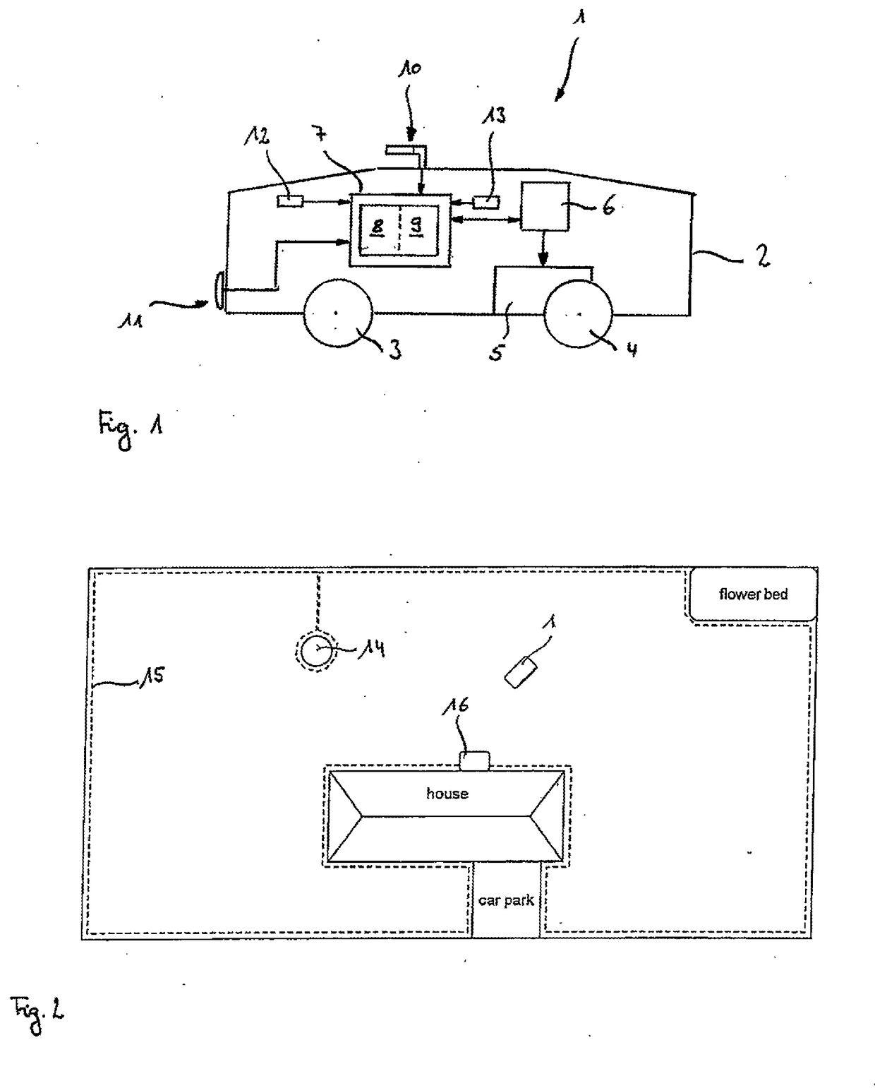
[0032]An overview about the structure of an autonomous vehicle which is in the following embodiments an autonomous lawn mower 1 is shown in FIG. 1. The autonomous lawn mower 1 is surrounded by a body work 2 that supports the different units and elements of the autonomous lawn mower 1. In particular, the body work 2 is connected to a plurality of wheels 3 and 4. At least a part of the wheels 3, 4 can be driven by a driving means 5 which in the illustrated embodiment is mechanically connected to wheel 4. In order to control the direction of driving of the autonomous lawn mower 1, the driving means 5 including for example an electric motor is connected to two wheels 4 of a rear axle of the autonomous lawn mower 1. By driving the wheels 4 of the rear axle with different rotational speeds, control of the driving direction of the autonomous lawn mower 1 is possible.

[0033]The driving means 5 is controlled by means of signals that are generated by a control unit 6 that is connected to the d...


PUM


Abstract

An autonomous vehicle comprises an environment sensing means for sensing an environment of the autonomous vehicle, and a computing unit configured to perform a mapping function and a localization function. The mapping function is based upon signals supplied from the environment sensing means to build a map. The localization function localizes the autonomous vehicle within the map and generates localization information. The autonomous vehicle further comprises boundary distance sensing means configured to generate a distance signal correlated to a distance between the autonomous vehicle and boundary indication means. The computing unit is configured to receive the distance signal and to perform the mapping function or the localization function based upon a signal from the environment sensing means and the distance signal from the boundary distance sensing means. The system also comprises a boundary wire indicating a border of an area in which autonomous driving of the vehicle can be performed.

Description

BACKGROUND[0001]Field[0002]The invention relates to an autonomous vehicle with a computing unit to perform a mapping function and a localization function of the vehicle within the map, in particular an autonomous gardening tool such as an autonomous lawn mower or scarifier and a system with such autonomous vehicle and a boundary wire indicating a border of an area in which autonomous driving of the autonomous vehicle shall be performed.[0003]Description of the Related Art[0004]Over the past few years, it became more and more popular to substitute tools like vacuum cleaners, lawn mowers or scarifier by self-propelled devices that are capable of driving on their own. Thus, no operator is needed that pushes and controls direction of such devices. Of course, the functionality of these devices has been improved over the product cycles up to now. Nevertheless, there are some disadvantages that might be annoying for some users. Maybe the biggest problem is that the driving direction of the...

Claims


Application Information

Patent Timeline
IPC IPC(8): G05D1/00G05D1/02
CPCG05D1/0088G05D1/0219G05D1/0251G05D1/027G05D1/0274G05D1/0265
Inventor FRANZIUS, MATHIASEINECKE, NILS
Owner HONDA RES INST EUROPE
Learn More