
Linear actuator assembly and system

a technology of actuators and assemblies, applied in the direction of machines/engines, liquid fuel engines, servomotors, etc., can solve the problems of increasing machine downtime, complicated use of hoses, pipes, fittings, etc., and achieve the effect of increasing the risk of pump cavitation or high fluid temperatur

Active Publication Date: 2017-04-27
PROJECT PHOENIX
View PDF11 Cites 11 Cited by
  • Summary
  • Abstract
  • Description
  • Claims
  • Application Information

AI Technical Summary

Benefits of technology

The patent describes a system and method for controlling the movement of a linear actuator in an industrial machine. The system uses a hydraulic actuator and a variable-speed or torque pump to provide precise control of the fluid flow and pressure in the system. The system also has fail-safe mode of operation to prevent pump cavitation or high fluid temperatures. The system has a compact design and is particularly useful in closed-loop hydraulic systems. The adjustment of the hydraulic fluid flow and pressure is done without the aid of another control device, making it more efficient and reliable. Overall, this technology provides a more compact and reliable design for linear actuators in industrial machines.

Problems solved by technology

However, these hydraulic systems can be relatively large and complex.
To interconnect these parts, various additional components like connecting shafts, hoses, pipes, and / or fittings are used in a complicated manner.
Moreover, these components are susceptible to damage or degradation in harsh working environments, thereby causing increased machine downtime and reduced reliability of the machine.
In addition, when a hydraulic pump fails because its motor has failed, there may be no safe way to shut down the system or to operate the system until the current operation has completed.

Method used


Image

  • Linear actuator assembly and system
  • Linear actuator assembly and system
  • Linear actuator assembly and system

Examples


Embodiment Construction

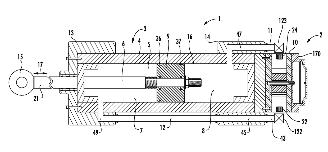
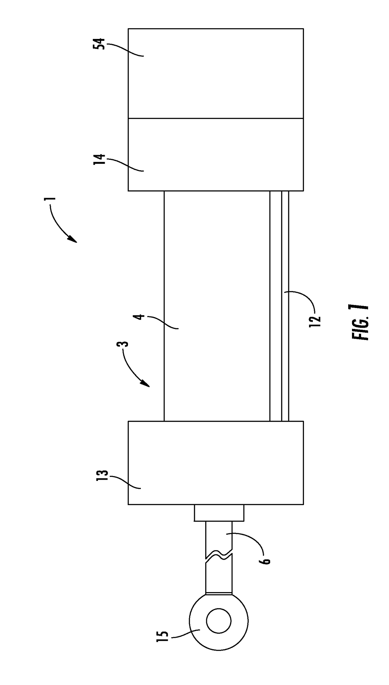
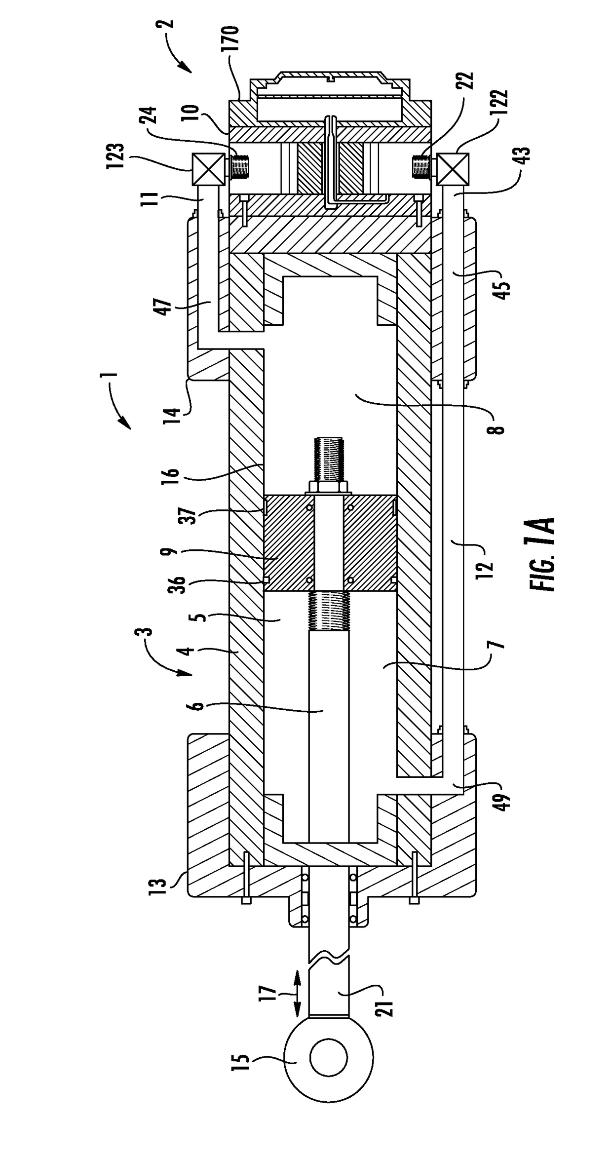
[0035]Exemplary embodiments of the present invention are directed to a linear actuator system with a linear actuator and at least one integrated pump assembly connected to the linear actuator to provide fluid to operate the linear actuator. The integrated pump assembly includes a pump with at least one fluid driver comprising a prime mover and a fluid displacement assembly to be driven by the prime mover such that fluid is transferred from a first port of the pump to a second port of the pump. The pump assembly also includes two valve assembles to isolate the pump from the system. The linear actuator system also includes a controller that establishes at least one of a speed and a torque of the at least one prime mover to exclusively adjust at least one of a flow and a pressure in the linear actuator system to an operational set point. The linear actuator system can include sensor assemblies to measure system parameters such as pressure, temperature and / or flow. When the linear actua...


PUM


Abstract

A linear actuator system includes a linear actuator and an integrated pump assembly connected to the linear actuator to provide fluid to operate the linear actuator. The integrated pump assembly includes a pump with two fluid drivers, each fluid driver comprising a prime mover and a fluid displacement assembly to be driven by the prime mover such that fluid is transferred from a first port of the pump to a second port of the pump. The pump assembly also includes two valve assembles to isolate the pump from the system. The linear actuator system also includes a controller that establishes the pump in a normal mode of operation in which the prime movers are independently driven and switches to a fail-safe mode of operation in which only one prime mover is operated.

Description

PRIORITY[0001]The present application claims priority to U.S. Provisional Patent Application Nos. 62 / 006,750 filed on Jun. 2, 2014; 62 / 007,719 and 62 / 007,723 filed on Jun. 4, 2014; 62 / 017,362, 62 / 017,395, and 62 / 017,413 filed on Jun. 26, 2014; 62 / 031,672, 62 / 031,353, and 62 / 031,597 filed on Jul. 31, 2014; 62 / 033,329 and 62 / 033,357 filed on Aug. 5, 2014; 62 / 054,176 filed on Sep. 23, 2014; 62 / 060,441 filed on Oct. 6, 2014; 62 / 066,261 filed on Oct. 20, 2014; and 62 / 072,132 filed on Oct. 29, 2014, which are incorporated herein by reference in their entirety.TECHNICAL FIELD[0002]The present invention relates generally to linear actuator assemblies and actuating methodologies thereof, and more particularly to a linear actuator assembly having a pump assembly and a linear actuator and control methodologies thereof in a fluid pumping system, including providing normal and fail-safe modes of operation.BACKGROUND OF THE INVENTION[0003]Linear actuator assemblies are widely used in a variety of...

Claims


Application Information

Patent Timeline
Patent Type & Authority Applications(United States)
IPC IPC(8): F15B11/10E02F9/22F15B15/14E02F3/42F04C2/14F15B15/18
CPCF15B11/10F15B2211/7054F15B15/18F15B15/14E02F3/425E02F9/2271F15B2211/41563F15B2211/41572F15B2211/5157F15B2211/5158F15B2211/6306F15B2211/6323F15B2211/6343F15B2211/6652F15B2211/6653F15B2211/6654F15B2211/6656F04C2/14F15B2211/3057F15B2211/632F15B2211/75F15B2211/76F04C2/18F04C15/008F04C15/06F04C2240/603F04C2240/40F04C2240/402F04C14/02F04C11/001F15B11/17F15B2211/20576F04C14/08F04C28/08F15B1/26F15B11/003F15B2211/2053F15B2211/275F15B2211/6651F15B2211/7053
Inventor AFSHARI, THOMAS
Owner PROJECT PHOENIX
Features
  • Generate Ideas
  • Intellectual Property
  • Life Sciences
  • Materials
  • Tech Scout
  • Unparalleled Data Quality
  • Higher Quality Content
  • 60% Fewer Hallucinations
Learn More