Device and method for controlling IC temperature

a technology of integrated circuits and temperature controls, which is applied in the direction of measurement devices, electronic circuit testing, instruments, etc., can solve the problems of difficult rapid cooling of the ic's core temperature, inability of cooling methods to maintain the tested ic at a constant temperature, and the temperature of such an ic tends to drop, so as to achieve rapid heating or cooling, improve efficiency, and improve efficiency

Active Publication Date: 2017-04-27
TEST21 TAIWAN
View PDF2 Cites 6 Cited by
  • Summary
  • Abstract
  • Description
  • Claims
  • Application Information

AI Technical Summary

Benefits of technology

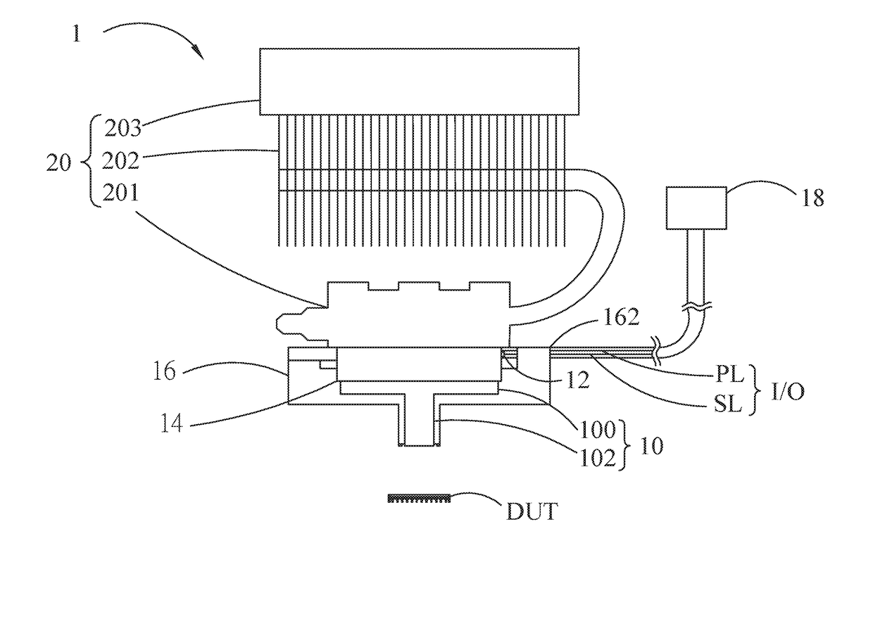
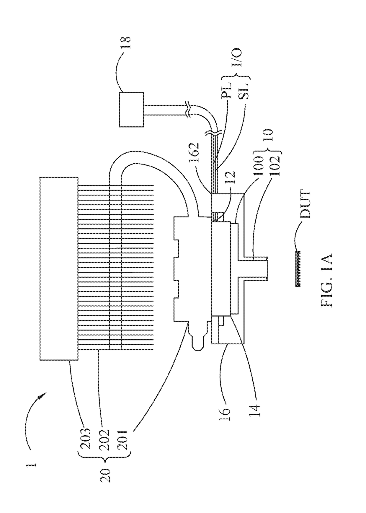
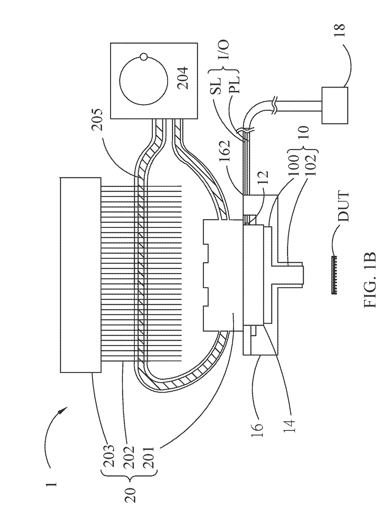
[0023]In conclusion, contrary to techniques known in the art, the device and method for controlling IC temperature of the present invention is capable of rapidly heating or cooling the IC in various sizes to a certain temperature, and precisely maintaining the temperature of the IC at a constant value for testing. Specifically, the device and method for controlling IC temperature of the present invention conducts heat by contacting the tested IC with the compressor, therefore the present invention heats up or cools down the IC by direct contact during the heating or cooling for IC performance test. So, in contrast to techniques known in the art, which transfer heat by using a fan to blow a stream of hot or cold air, the present invention is faster, simpler, more economic, more convenient, saves more power and so is more environmentally friendly. Besides, the heat insulating structure with a plurality of heat insulating walls and an outer wall forms a plurality of heat insulating air walls which effectively block unwanted thermal energy from entering the DUT during cooling or effectively prevent the unwanted loss of thermal energy during heating, such that the rate of heating or cooling of the DUT is accelerated accordingly.
[0024]Furthermore, the temperature controller of the present invention is capable of accurately measuring the temperature of the temperature controlling element when the temperature controlling element, compressor and DUT reaches thermal equilibrium due to the closed loop formed by the power line, signal line, and the temperature controller, thereby being highly adaptable and accelerating efficiency during measuring. Furthermore, the present invention may be disposed with the cooling plate and the reversing switch to achieve the function of heating and cooling without the need for additional elements.

Problems solved by technology

So in certain countries with polar climate, the temperature of such an IC tends to drop due to the extremely cold surroundings.
However, since the cooling agent does not come into contact with the tested IC directly, it is difficult for the cooling agent to quickly lower the IC's core temperature despite it being able to lower its overall temperature.
On top of that, such a cooling method cannot maintain the tested IC at a constant temperature.
However, since the hot plate is no longer able to supply heat to the IC once it has left the hot plate, the IC's temperature drops due to thermal convection in the air while the IC is being moved from the hot plate to the socket and thermal conduction to the socket while the IC is in contact with the socket.
Thus, such a heating method fails to maintain the tested IC at a constant temperature.
It follows that the test results are inconsistent, since the IC is not tested under the intended constant temperature.
(1) Since the heat gun only heats up a specific area with hot air, the IC might not be heated up evenly.
The temperature of the hot air cannot be precisely controlled, so the temperature of the hot air might be too high or insufficient.
Also, even though the tested IC is thermally insulated by the thermal insulating structure, the hot air of the heat gun might still affect the temperature of the components around the tested IC.
The IC then starts to slowly cool and no longer maintains the desired temperature during testing.
(3) When the heat gun is heating the tested IC, the components around the IC and the PCB might be heated as well, so the test results might be inaccurate.
This test socket and lid stand in the way of the hot air from the heat gun, thereby making it difficult to heat up the small IC.
(5) There is no way to determine the temperature of the IC during testing, let alone the required heating duration.
This system is pricey and bulky, consumes a lot of power, and requires compressed gas or air from a compressor to operate.
Furthermore, since the tested IC is disposed in the test socket and is of a small size, it might be difficult to heat up or cool down such an IC by applying a stream of hot or cold air.
Moreover, the temperature sensor of the thermal stream system is usually disposed at a position where the thermal stream passes, so the temperature sensor will not accurately reflect the temperature of the tested IC.
Besides, while it is possible to connect an IC thermocouple to the thermal stream system in order to obtain the IC's temperature, such a thermocouple is usually not disposed in the IC in the testing phase.
The above mentioned method for heating or cooling the IC is extremely inconvenient and is also incapable of obtaining an accurate temperature reading of the IC.
However, the operation of thermal stream system on smaller ICs may be hindered due to the socket blocking the flow of air.
Also, in particular, there is the need to wait and the extra use of electricity due to the time it takes, usually above 30 minutes, for the thermal stream system to heat up or cool down the IC.
Hence, such a solution is not convenient to use and renders the IC test inefficient.
So, the thermal stream system is not capable of solely heating up or cooling down the IC, which leads to the likely deviation from optimum working temperatures of the surrounding components.
Therefore, the results for the IC test are significantly affected.
In addition, because the surrounding components tend to deviate from optimum working temperatures, locating any faulty ICs will be a challenging task when testing a plurality of ICs.
This is thus an inconvenient method for temperature testing of ICs.

Method used


Image

  • Device  and  method  for  controlling  IC temperature
  • Device  and  method  for  controlling  IC temperature
  • Device  and  method  for  controlling  IC temperature

Examples


first embodiment

[0051]FIG. 2A is the plan view illustrating the heat insulating structure according to the device for controlling IC temperature of the present invention. The heat insulating structure 16 may include an upper base 161, a lower base 162 and an outer wall 163 cooperatively forming the heat insulating recess 165. An upper hollow portion 1611 is disposed at the center of the upper base 161. The lower base 162 is disposed opposite to the upper base 161, and a lower hollow portion 1621 is located at the center of the lower base 162. The outer wall 163 is interposed between the upper base 161 and the lower base 162 along the outermost region of the upper base 161 and the lower base 162. When the heat insulating structure 16, temperature controlling element 14 and base 100 of the compressor 10 are assembled, an enclosed space is formed. The enclosed space has the air layer for heat insulation. The air layer may effectively prevent the temperature controlling element 14 and the compressor 10...

second embodiment

[0052]FIG. 2B is the plan view illustrating the heat insulating structure according to the device for controlling IC temperature of the present invention. As shown in the figure, a plurality of heat insulating walls 164 form a plurality of heat insulating recesses 165 in between the upper base 161 and the lower base 162, wherein the plurality of heat insulating walls 164 extend from the outer wall 163 to the center of the heat insulating structure 16. The plurality of heat insulating walls 164 are laid against the temperature controlling element 14 and the base 100 of the compressor 10, whereas the upper hollow portion 1611, the lower hollow portion 1621 and the plurality of heat insulating walls 164 cooperatively form the accommodation space.

[0053]It is noteworthy that the line to surface contact is formed when the plurality of heat insulating walls 164 are laid closely against the temperature controlling element 14 and the base 100 of the compressor 10, i.e., the contact surface i...


PUM


Abstract

A device for controlling IC temperature capable of bringing a device-under-test to a predetermined temperature includes a compressor, temperature controller element, thermal sensing element, heat insulating structure, input / output terminal and a temperature controller. The compressor has a base and a contact portion contacting the DUT directly. The thermal sensing element is attached to the temperature controlling element contacting the base. The heat insulation structure surrounds the temperature controlling element and a portion of the compressor. The input / output terminal, having a signal line and at least one power line, is disposed on the heat insulation structure. The power and signal lines connected to the temperature sensor are connected to the temperature controlling element and thermal sensing element respectively. The temperature sensor powers the temperature controlling element and controls temperature thereof. Temperature of the temperature controlling element is obtained by measuring electrical properties of thermal sensing element via signal line.

Description

CROSS-REFERENCE TO RELATED APPLICATION[0001]This application claims priority from Taiwan Patent Application Nos. 104135144 and 105105674, filed respectively on Oct. 26, 2015 and Feb. 25, 2016, in the Taiwan Intellectual Property Office, the contents of which are hereby incorporated by reference in their entirety for all purposes.BACKGROUND OF THE INVENTION[0002]1. Field of the Invention[0003]The present invention relates a device and method for controlling integrated circuit (IC) temperature. More precisely, the present invention relates to a device and method for controlling IC temperature applicable to heating or cooling the IC and detecting the temperature thereof during IC performance test.[0004]2. Description of the Related Art[0005]Specifically, the miniscule IC inside the portable electronic device has a low wattage, i.e. approximately less than 2 W or even approximately 1 mW, thereby generating very little heat. So in certain countries with polar climate, the temperature of ...

Claims


Application Information

Patent Timeline
Patent Type & Authority Applications(United States)
IPC IPC(8): G01R31/28
CPCG01R31/2874
Inventor HO, SHUN-BON
Owner TEST21 TAIWAN
Why Eureka
Try Eureka