Fuel filling apparatus and method for bi-fuel vehicle

a fuel tank and bi-fuel technology, applied in the direction of machines/engines, liquid transfer devices, containers discharging methods, etc., can solve the problems of inability to fill lpg fuel tanks, and achieve the effect of reducing the pressure of the fuel tank

Inactive Publication Date: 2017-05-04
HYUNDAI MOTOR CO LTD
View PDF23 Cites 8 Cited by
  • Summary
  • Abstract
  • Description
  • Claims
  • Application Information

AI Technical Summary

Benefits of technology

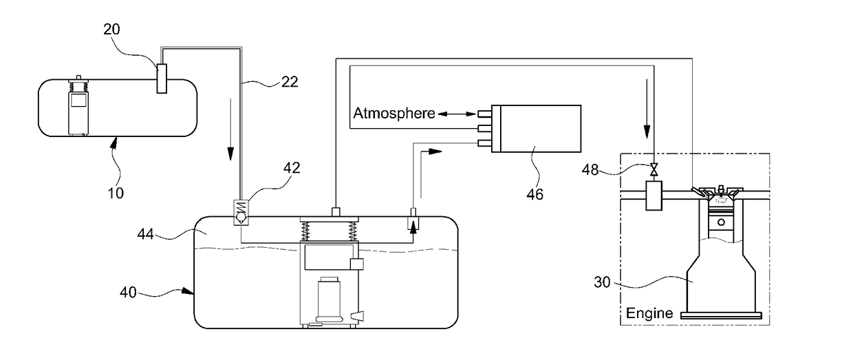
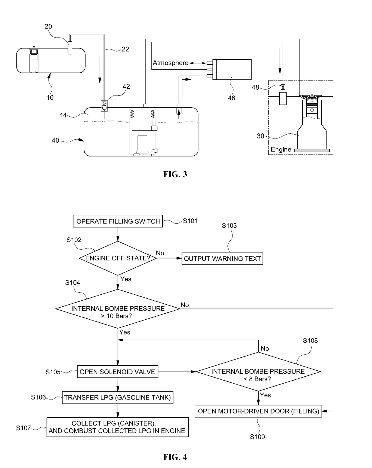
[0008]The present invention provides a fuel filling apparatus and method for a bi-fuel vehicle capable of temporarily burning a portion of liquefied petroleum gas (LPG) fuel after collecting the fuel portion, using a gasoline fuel tank and a canister, when the internal pressure of an LPG fuel tank in the bi-fuel vehicle is greater than an LPG filling pressure of a filling gun, to decrease the internal pressure of the LPG fuel tank to a level below the LPG filling pressure of the filling gun, thereby achieving smoother LPG fuel filling of the LPG fuel tank using the filling gun.
[0014]Through the above-described configurations, the present invention provides the following effects.
[0015]In accordance with the present invention, when the LPG fuel tank pressure of the bi-vehicle is equal to or greater than the LPG filling pressure of the filling gun due to an excessive increase in ambient temperature for example, in summer, a portion of the LPG fuel in the fuel tank may be guided to the upper expansion space of the gasoline tank, and may be combusted in the engine after being collected by the canister. Accordingly, it may be possible to decrease the fuel tank pressure below the filling pressure of the filling gun and, as such, filling the fuel tank with the LPG fuel using the filling gun may be more smoothly achieved.

Problems solved by technology

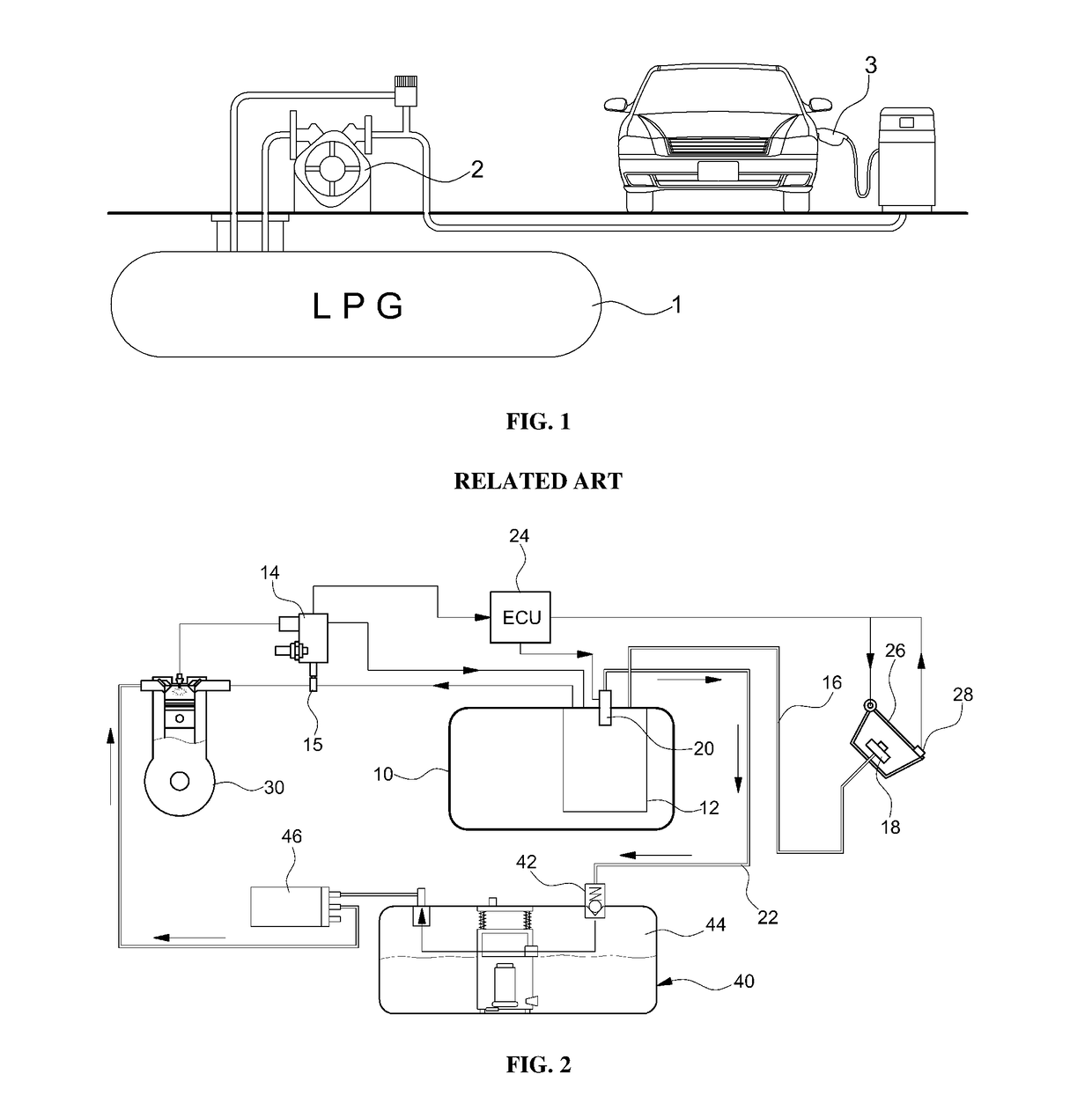
In summer or during warmer temperatures, however, there may be a problem in that LPG fuel filling is impossible when the internal pressure of the LPG fuel tank in the vehicle increases above an LPG filling pressure due to high ambient temperature.
As a result, there may be a problem in that the LPG fuel tank is not able be filled with LPG fuel through the filling gun.

Method used


Image

  • Fuel filling apparatus and method for bi-fuel vehicle
  • Fuel filling apparatus and method for bi-fuel vehicle
  • Fuel filling apparatus and method for bi-fuel vehicle

Examples


Embodiment Construction

[0021]It is understood that the term “vehicle” or “vehicular” or other similar term as used herein is inclusive of motor vehicles in general such as passenger automobiles including sports utility vehicles (SUV), buses, trucks, various commercial vehicles, watercraft including a variety of boats and ships, aircraft, and the like, and includes hybrid vehicles, electric vehicles, plug-in hybrid electric vehicles, hydrogen-powered vehicles and other alternative fuel vehicles (e.g. fuels derived from resources other than petroleum). As referred to herein, a hybrid vehicle is a vehicle that has two or more sources of power, for example both gasoline-powered and electric-powered vehicles.

[0022]Although exemplary embodiment is described as using a plurality of units to perform the exemplary process, it is understood that the exemplary processes may also be performed by one or plurality of modules. Additionally, it is understood that the term controller / control unit refers to a hardware devi...


PUM


Abstract

A fuel filling apparatus and method for a bi-fuel vehicle using both gasoline and liquefied petroleum gas (LPG) as a fuel are provided to. The fuel filling apparatus and method are capable of temporarily burning a portion of LPG fuel after collecting the fuel portion, using a gasoline fuel tank and a canister, when the internal pressure of an LPG fuel tank in the bi-fuel vehicle is equal to or greater than an LPG filling pressure of a filling gun. Additionally, the internal pressure of the LPG fuel tank is decreased to a level below the LPG filling pressure of the filling gun, thereby achieving smoother LPG fuel filling of the LPG fuel tank by the filling gun.

Description

CROSS-REFERENCE TO RELATED APPLICATION[0001]This application claims under 35 U.S.C. §119(a) the benefit of priority to Korean Patent Application No. 10-2015-0151728 filed on Oct. 30, 2015, the entire contents of which are incorporated herein by reference.BACKGROUND[0002](a) Technical Field[0003]The present disclosure relates to a fuel filling apparatus and method for a bi-fuel vehicle, and more particularly to a fuel filling apparatus and method for a bi-fuel vehicle using both gasoline and liquefied petroleum gas (LPG) as a fuel to more easily fill an LPG fuel tank with LPG.[0004](b) Background Art[0005]Generally, in a bi-fuel vehicle using both gasoline and liquefied petroleum gas (LPG) as a fuel, a system for supplying a gasoline fuel to an engine and a system for supplying LPG fuel to the engine are configured to be separate from each other and, as such, gasoline fuel filling and LPG fuel filling are performed in a separate manner.[0006]As shown in FIG. 1, LPG fuel filling in th...

Claims


Application Information

Patent Timeline
Patent Type & Authority Applications(United States)
IPC IPC(8): B60K15/035B67D7/32B67D7/04F02M37/00B60K15/04
CPCB60K15/03519F02M37/0064B60K15/04B67D7/04B67D7/3281B67D2007/329B60K2015/03302B60K2015/03355B60K2015/03576B60K2015/03585B60K2015/0319F17C5/02F17C13/025F17C13/04F17C2201/0109F17C2201/035F17C2205/0323F17C2205/0335F17C2221/035F17C2223/0153F17C2227/0135F17C2250/043F17C2265/061B60K15/03006B60K2015/03026B60K2015/03203B60K2015/0321F02D19/0647F02D19/0665F02M21/0212F02M21/0224F02M25/08F02M25/089Y02T10/30
Inventor KIM, CHANG HANKIM, JONG KIPARK, JAE HWALEE, JAE MIN
Owner HYUNDAI MOTOR CO LTD
Why Eureka
Try Eureka