Iris Recognition Device, Manufacturing Method Therefor and Application Thereof

Active Publication Date: 2017-05-04
NINGBO SUNNY OPOTECH CO LTD
View PDF2 Cites 20 Cited by
  • Summary
  • Abstract
  • Description
  • Claims
  • Application Information

AI Technical Summary

Benefits of technology

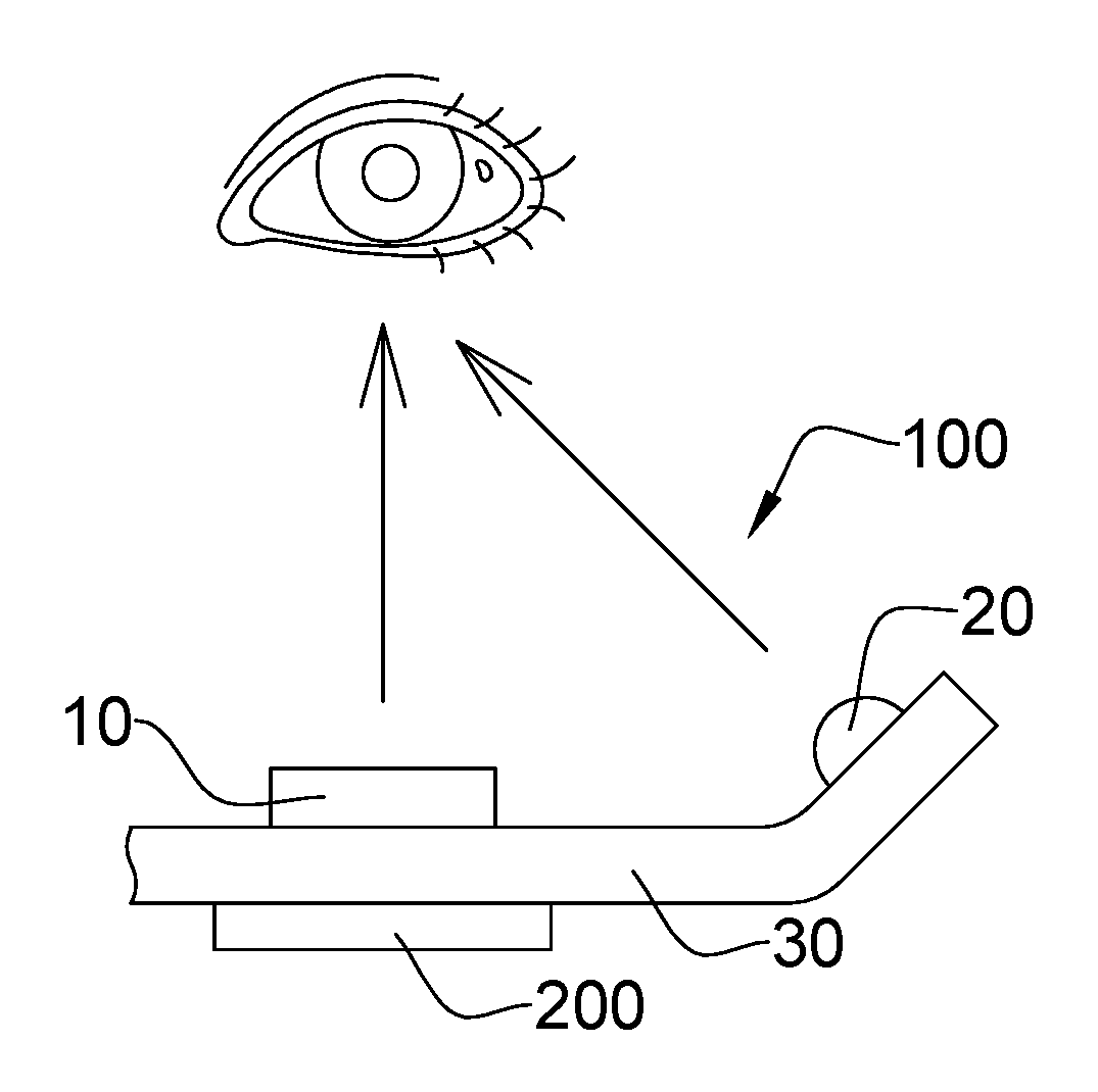
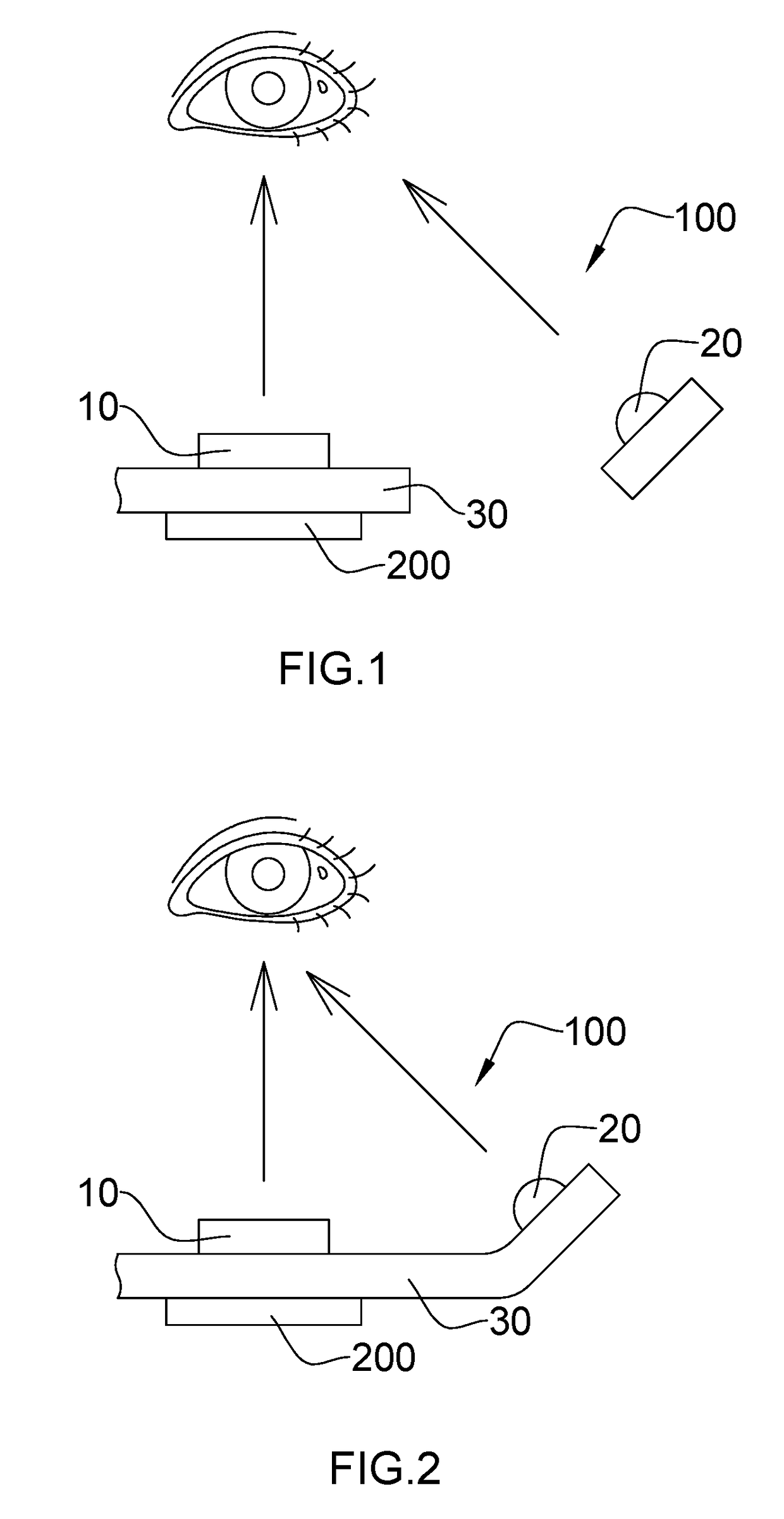
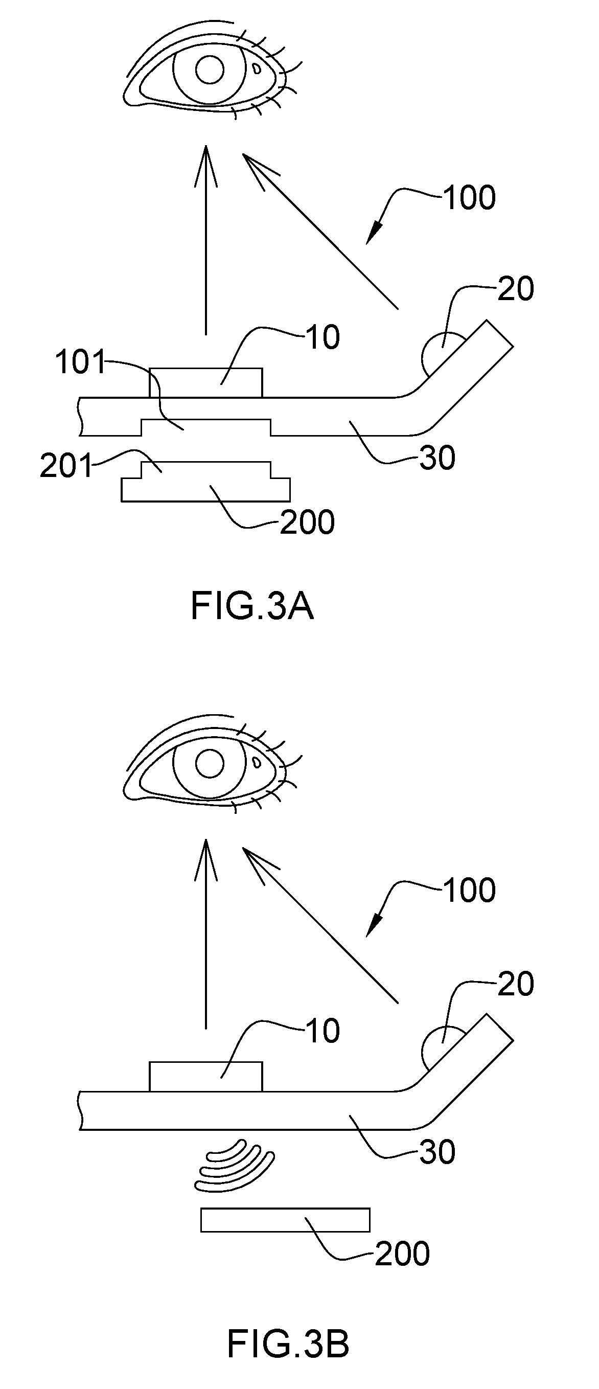
[0012]Another advantage of the invention is to provide an iris recognition device, a manufacturing method for the iris recognition device, and an application of the iris recognition device, wherein the fill light method can form a uniform brightness in the user's iris region, thereby improving precision of the collected iris characteristics of the user.
[0013]Another advantage of the invention is to provide an iris recognition device, a manufacturing method for the iris recognition device, and an application of the iris recognition device, wherein a fill light component is provided and the fill light component provides infrared lights as a supplementary light source when the fill light component collects the iris characteristics of the user in order to ensure that the images carrying the collected iris characteristics meet the requirements of the iris recognition, and that the fill light component effectively improves precision of the collected iris characteristics and reduces the consumed user identification time.
[0014]Another advantage of the invention is to provide an iris recognition device, a manufacturing method for the iris recognition device, and an ap

Problems solved by technology

However, the required software and logic which are in response to and perform the process of touching and pressing are complex, so that the system matching user information costs a longer time, and the accuracy of the matching results is not effectively guaranteed.
In other words, the recognition technology based on the touch technology may has a wrong matching result, as a result, it not only brings unnecessary trouble to the user, but also is a threat to the user's information security.
However, the traditional iris recognition technology also has many problems to limit performances.
On one hand, the traditional iris recognition technology has a low image quality to collect a user's iris characteristics, and can only be collected at a close range.
Once the distance is relatively far, it c

Method used


Image

  • Iris Recognition Device, Manufacturing Method Therefor and Application Thereof
  • Iris Recognition Device, Manufacturing Method Therefor and Application Thereof
  • Iris Recognition Device, Manufacturing Method Therefor and Application Thereof

Examples


first embodiment

[0518]Combined with one or more objects of the present invention, as shown in FIG. 39 to FIG. 43 of the drawings, in a first preferred embodiment of the present invention, a first lens 1000, a second lens 2000 and a third lens 3000 of the camera optics lens assembly are subsequently arranged from the object side to the image side (as shown in FIG. 39 of the drawings from left to right), the camera optics lens assembly is provided with an image sensor chip 111, wherein a side surface of the image sensor chip 111 which towards the camera optics lens assembly is defined as an imaging surface 1111.

[0519]It is worth mentioning that an infrared filter 4000 is provided between the camera optics lens assembly and the human face camera module 40, in particular, the infrared filter 4000 is provided between the third lens 3000 and the human face camera module 40 to produce the iris camera module and to make the iris camera module to form the infrared iris camera module, so that when the iris c...

second embodiment

[0535]As shown in FIG. 44 to FIG. 48 of the drawings, in a second preferred embodiment of the present invention, a first lens 1000, a second lens 2000 and a third lens 3000 of the camera optics lens assembly are subsequently arranged from the object side to the image side (as shown in FIG. 44 of the drawings from left to right), the camera optics lens assembly is provided with an image sensor chip 111, wherein a side surface of the image sensor chip 111 which towards the camera optics lens assembly is defined as an imaging surface 1111.

[0536]In this embodiment, the first lens 1000 is a lens having a positive focal power to provide a positive refractive power, the second lens 2000 is a lens having a negative focal power to provide a negative refractive power, and the third lens 3000 is a lens having a negative focal power to provide a negative refractive power. Wherein the first lens object side surface 1200 is a convex surface, the second lens object side surface 2200 is a concave s...

third embodiment

[0551]As shown in FIG. 49 to FIG. 53 of the drawings, in a third preferred embodiment of the present invention, a first lens 1000, a second lens 2000 and a third lens 3000 of the camera optics lens assembly are subsequently arranged from the object side to the image side (as shown in FIG. 49 of the drawings from left to right), the camera optics lens assembly is provided with an image sensor chip 111, wherein a side surface of the image sensor chip 111 which towards the camera optics lens assembly is defined as an imaging surface 1111.

[0552]In this embodiment, the first lens 1000 is a lens having a positive focal power to provide a positive refractive power, the second lens 2000 is a lens having a negative focal power to provide a negative refractive power, and the third lens 3000 is a lens having a negative focal power to provide a negative refractive power. Wherein the first lens object side surface 1200 is a convex surface, the second lens object side surface 2200 is a concave su...


PUM


Abstract

The iris recognition device includes an iris camera module used for collecting iris characteristics of a user, and at least one fill light component used for providing a supplementary light source for the iris camera module. When the iris recognition device is used for collecting the iris characteristics of the user, the supplementary light source provided by the fill light component reduces reflective spots on the iris or make reflective spots in areas other than iris such as sclera and pupil, thereby improving precision of the collected iris characteristics of the user.

Description

CROSS REFERENCE OF RELATED APPLICATION[0001]This is a non-provisional application that claims priority to international application number PCT / CN2015 / 079363, international filing date May 20, 2015, the entire contents of each of which are expressly incorporated herein by reference.NOTICE OF COPYRIGHT[0002]A portion of the disclosure of this patent document contains material which is subject to copyright protection. The copyright owner has no objection to any reproduction by anyone of the patent disclosure, as it appears in the United States Patent and Trademark Office patent files or records, but otherwise reserves all copyright rights whatsoever.BACKGROUND OF THE PRESENT INVENTION[0003]Field of Invention[0004]The present invention relates to an optical imaging device, and more particularly to an iris recognition device, a manufacturing method therefor, and an application thereof.[0005]Description of Related Arts[0006]With the development of the Internet and its applications, identi...

Claims


Application Information

Patent Timeline
IPC IPC(8): G06K9/00H04N5/33G06K9/20G06V10/141G06V10/147
CPCG06K9/00617G06K9/0061G06K9/00604G06K9/2036G06K9/00281G06K9/209G06K9/00228G06K9/00288H04N5/33G02B13/18G06F21/32G06V40/19G06V10/141G06V10/147H04N23/56H04N23/57G06F18/00G06V40/197G06V40/193G06V40/161G06V40/171G06V40/172
Inventor GU, YIWULUO, MENGJIETANG, XINKEXU, JIEWEIXU, SHIXINHUANG, LIN
Owner NINGBO SUNNY OPOTECH CO LTD
Why Eureka
Try Eureka