Wearing-type movement assistance device

a technology of movement assistance and wearables, which is applied in the field of wearable-type movement assistance devices, can solve the problems of insufficient degree, type differences, and inability to cope with the movement of upper limbs and trunks necessary for work in some cases, so as to reduce the load to the waist, improve the working efficiency, and ensure the degree of freedom of the upper body

Active Publication Date: 2017-05-25
CYBERDYNE INC +1
View PDF2 Cites 18 Cited by
  • Summary
  • Abstract
  • Description
  • Claims
  • Application Information

AI Technical Summary

Benefits of technology

[0019]According to the present invention, an intermediate joint is provided between a shoulder joint and an elbow joint to achieve a redundant degree of freedom, and thus even when joints of a wearer and the device do not have the same rotational axis, the difference of positional relationship between the joints is absorbed, and a body type difference between wearers can be coped with. Also, a sufficient degree of freedom of the upper body can be ensured. Also, a combination with a waist assistant device having a lower limb drive unit cancels a reaction force of an assistance force transmitted to the waist from the upper limb assistance device, and reduces the load to the waist of a wearer, thereby making it possible to assist anti-gravity work using an upper limb and to improve the working efficiency.

Problems solved by technology

However, the above-mentioned conventional upper limb assistance device does not sufficiently ensure a degree of freedom of the upper body necessary for work on a ceiling surface or the like, and cannot cope with movement of the upper limbs and the trunk necessary for the work in some cases.
In addition, there are some cases where a body type difference such as a difference in length, thickness of the limbs between wearers cannot be coped with.

Method used


Image

  • Wearing-type movement assistance device
  • Wearing-type movement assistance device
  • Wearing-type movement assistance device

Examples


Embodiment Construction

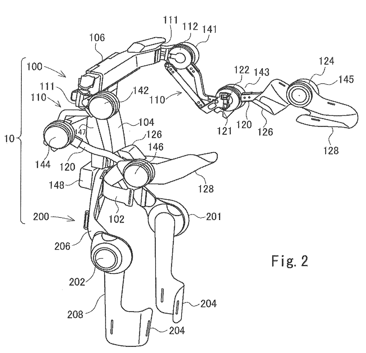
[0032]Hereinafter, an embodiment of the present invention will be described based on the drawings.

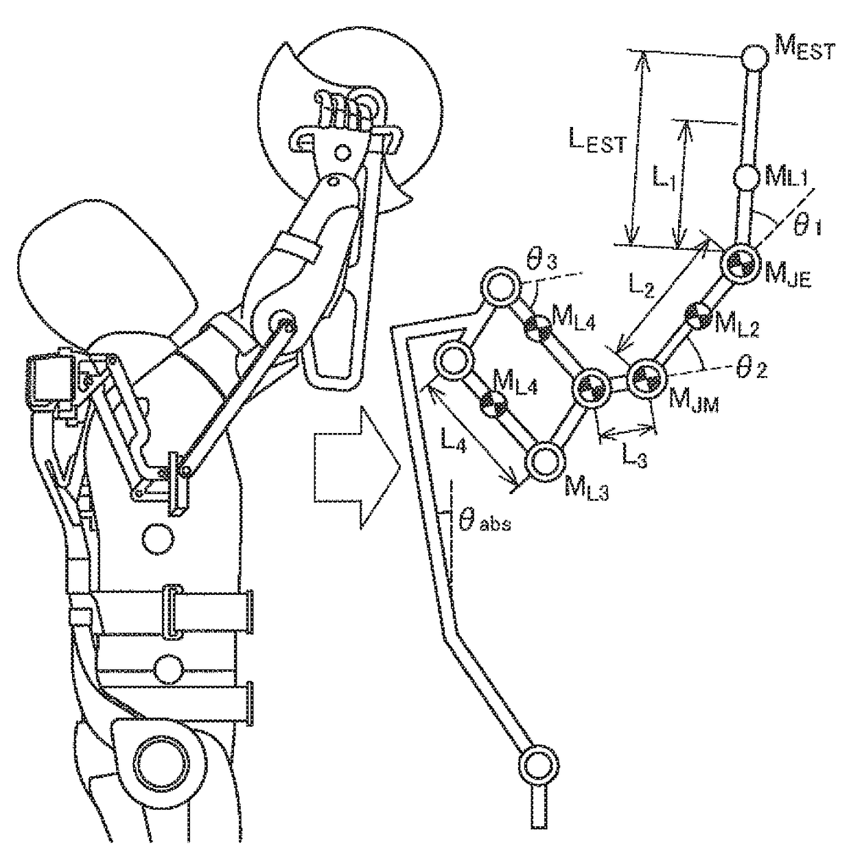
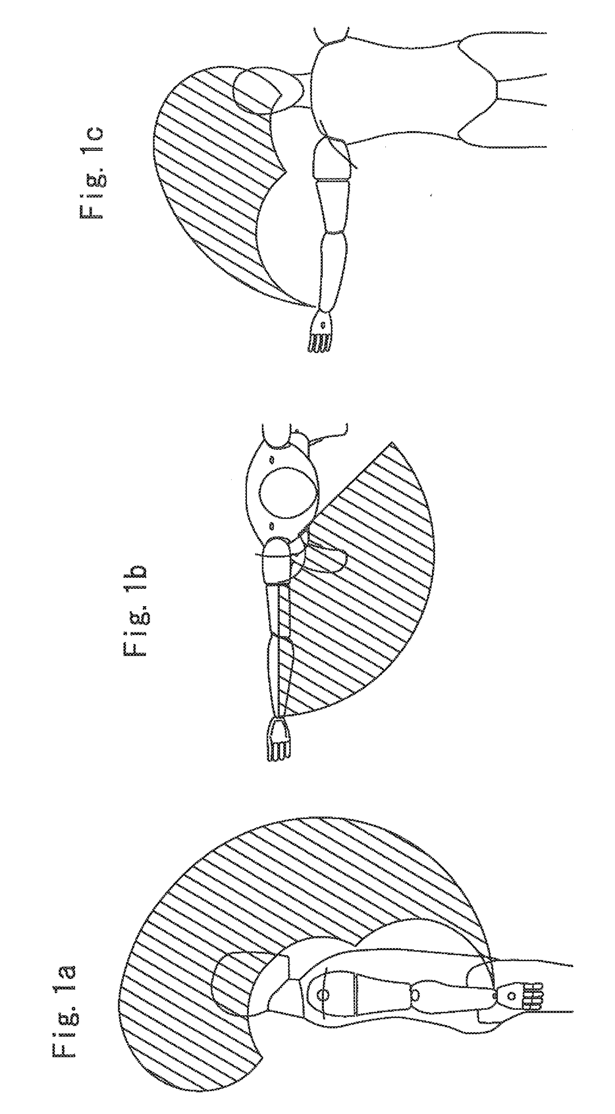
[0033]In work with a lifted posture of the upper limbs maintained, a tool is grasped in front of the body and is used by lifting the tool above. Therefore, in the wearing-type movement assistance device according to the present embodiment, the movable range of a hand is set in front of and above a wearer. Also, regarding the movable range of the trunk, the degree of freedom of the lumbar spine included in the spinal column is assumed to be restricted. This is because the waist assistance device fixes the lumbar spine and provides movement assistance while reducing the load to the endoskeleton system.

[0034]The following Table 1 shows presumed movable ranges of joints of a human body.

TABLE 1PresumedMovable RangePartMovement[deg]TrunkRotation33Lateral Bending25Forward Bending23Rearward Bending12ElbowBending140Extension0Pronation90Supination90ShoulderBending163Extension5Horizontal Bending14...


PUM


Abstract

A wearing-type movement assistance device includes a frame to be worn on an upper limb of a wearer, a drive unit provided in each of joints of the frame, a biomedical signal detection unit detecting a biological potential signal of the wearer, a joint angle detection unit detecting an angle of each joint, and a control unit controlling the drive unit based on the biological potential signal and the angle of each joint. The frame includes a vertical frame, a shoulder frame that is laterally provided in a shoulder width direction from an upper end of the vertical frame, a first arm frame having one end coupled to the shoulder frame via a shoulder joint unit, and a second arm frame having one end coupled to the other end of the first arm frame via an intermediate joint unit and the other end connected to an elbow joint unit.

Description

TECHNICAL FIELD[0001]The present invention relates to a wearing-type movement assistance device that assists anti-gravity work using upper limbs.BACKGROUND ART[0002]In a construction site or the like, there are cases where work is conducted while an upper limb lifted posture, in which a tool such as a machine tool or a camera is held up, being maintained. Such anti-gravity work using the upper limb applies a heavy load is applied to muscle groups of the upper limb, and thus continuous work is difficult. Particularly, when a tool with a heavy weight is used, the working efficiency decreases significantly.[0003]For this reason, as a device that provides movement assistance for anti-gravity work, a wearing-type upper limb assistance device to be worn according to the skeletal outline a worker has been proposed (see, for instance, PTL 1).[0004]PTL 1: Japanese Unexamined Patent Application Publication No. 2008-295696SUMMARY OF INVENTION[0005]However, the above-mentioned conventional uppe...

Claims


Application Information

Patent Timeline
Patent Type & Authority Applications(United States)
IPC IPC(8): B25J9/16B25J17/00B25J9/00
CPCB25J9/1694B25J9/0006Y10S901/46B25J17/00Y10S901/15B25J9/0009A61H1/0281A61H2201/165
Inventor SANKAI, YOSHIYUKI
Owner CYBERDYNE INC
Why Eureka
Try Eureka